• Steel Soldiers now has a few new forums, read more about it at: New Munitions Forums!

  • Microsoft MSN, Live, Hotmail, Outlook email users may not be receiving emails. We are working to resolve this issue. Please add support@steelsoldiers.com to your trusted contacts.

Dual Circuit Brake Engineering Thread

tobyS

Well-known member
4,832
833
113
Location
IN
Great Peashooter...that's just what I needed...thanks. I'll plan for modification of the pin.

I'd be worrying more about capacity of the MC going to the 1 1/2" if I were not going to 4x4. That should not be a problem.

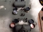
Since I have never had the deuce apart to see, the pin has a center that fits the cup on the 37317 (in the links) but the standard cup for the 1 3/8 size is flat inside. How does the pin stay centered in the flat cup?
 

Attachments

peashooter

Well-known member
1,038
205
63
Location
Hanover, minnesota
Great Peashooter...that's just what I needed...thanks. I'll plan for modification of the pin.

I'd be worrying more about capacity of the MC going to the 1 1/2" if I were not going to 4x4. That should not be a problem.

Since I have never had the deuce apart to see, the pin has a center that fits the cup on the 37317 (in the links) but the standard cup for the 1 3/8 size is flat inside. How does the pin stay centered in the flat cup?
it shouldn’t be a flat cup. Check out the last photo in post 11 here (it shows the face of both wheel cylinders where the link pins mate) https://www.steelsoldiers.com/showt...el-Cylinders&p=1538032&viewfull=1#post1538032
 

tobyS

Well-known member
4,832
833
113
Location
IN
it shouldn’t be a flat cup. Check out the last photo in post 11 here (it shows the face of both wheel cylinders where the link pins mate) https://www.steelsoldiers.com/showt...el-Cylinders&p=1538032&viewfull=1#post1538032
Yes, that was the photo caught my attention to begin with after you sent the link. I hoped to buy just pistons with the V for mine but Wagner says they are only available as a complete unit. Pistons are not available separately.

I thought I was good to go with a full new set....NOT...that's what I get for thinking.

Wagner gave me the number WC-746 for the cylinder with the 1 1/2" piston and the inverted V but that is a hard to find number. It crosses to WC-37317, so I ordered one from Oreilly to see if the piston is correct. Will report back tomorrow.
 

jkcondrey

Active member
Steel Soldiers Supporter
317
141
43
Location
Rutherfordton, NC
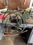
Well the original dual master has not panned out yet. Maybe I will get back around to fooling with it. In the meantime I bought this off the auction site. I believe its from an A3. I saw where another person had adapted it over to work with the clutch. I guess this weekend will be spent removing the old bracket/master and lining things up for fitment. Its fairly complete, has lines in decent shape and has the lines for the remote reservoir. Says it was a running vehicle(no mention of stopping though lol).
 

Attachments

jkcondrey

Active member
Steel Soldiers Supporter
317
141
43
Location
Rutherfordton, NC
So I have gotten my dual master with pedal assembly, another air pack and another air tank in order to split my brakes. After looking at the split brake TM, it only shows two air tanks. Do I need to install a third or was this just a suggestion in some of the posts, as I do not see a third tank in the line diagrams. Another one has a dryer installed, but again, I'm not sure if I need to plumb in a third or if I should just plumb in the new dual and second air pack. Any input is appreciated.
 

clinto

Moderator, wonderful human being & practicing Deuc
Staff member
Administrator
Super Moderator
Steel Soldiers Supporter
Supporting Vendor
12,596
1,133
113
Location
Athens, Ga.
So I have gotten my dual master with pedal assembly, another air pack and another air tank in order to split my brakes. After looking at the split brake TM, it only shows two air tanks. Do I need to install a third or was this just a suggestion in some of the posts, as I do not see a third tank in the line diagrams. Another one has a dryer installed, but again, I'm not sure if I need to plumb in a third or if I should just plumb in the new dual and second air pack. Any input is appreciated.
So, on the dual circuit M44A2 and all M44A3 systems, the way they did this was one of the tanks is internally divided, giving it two chambers. That's why one of the air tanks has two draincocks.

You can add a third tank, cut yours in half, weld a divider and reweld the two halves back together and add another bung for airflow output or find a set of takeoff M44A3 tanks.
 

tobyS

Well-known member
4,832
833
113
Location
IN
Thanks Peashooter for the heads up on the pin length when changing to 1 1/2" wheel cylinders.

I need to confirm my plan re the brakes for my A3 being made into a 4x4, thus 2 less cylinders in the rear. I believe peashooter said the A3 master cylinder is 50/50.

I'm going to 1 1/2" brake cylinders on the rear, so will have the same size all the way around (not have smaller on back).

Is there any problems I'm not aware of when going this route of 50/50 master cylinder and 1 1/2" brake cylinders (X4)? It would seem to be well balanced.
 

peashooter

Well-known member
1,038
205
63
Location
Hanover, minnesota
Is there any problems I'm not aware of when going this route of 50/50 master cylinder and 1 1/2" brake cylinders (X4)? It would seem to be well balanced.
I’m not aware of any issues either, it sounds ideal to me. Just make sure to route the larger of the fluid ports to the front axle.
 

tobyS

Well-known member
4,832
833
113
Location
IN
Sorry but I haven't been under to see yet, I'm working on the frame and axle mounts right now with the bed off.

I would assume the large port OEM on the A3 goes to the back, since it's operating 4 cylinders. You recommend changing so the front has the larger line? Would you carry the larger line to the T also or is it just bigger at the fitting?

I would appreciate a link to an air diagram. I'm confused with what appear to be check valves and I'm just now understanding. one air tank has two circuits (now that they are removed and will be relocated)
 
Last edited:

jkcondrey

Active member
Steel Soldiers Supporter
317
141
43
Location
Rutherfordton, NC
So I have finished up my conversion using the a3 parts. Brake bracket, pedal installed, third air tank for more air, dual air packs. Everything is plumbed, bleed today and have firm pedal, but now the vent tube behind turbo at firewall is gushing air. No fluid seems to be spraying, just air from compressor. Did I cross up a line or is an air pack bad? Any quick pointers?
 

jkcondrey

Active member
Steel Soldiers Supporter
317
141
43
Location
Rutherfordton, NC
The original air pack was just rebuilt. The second air pack was a working pull off of another truck. Incidentally, prior to starting the dual conversion, i had rebuilt the original air pack because i had fluid spraying out of the very same vent. Now its just constant air. I'm at a loss. If the rebuild fixed the original air pack, could i just have the air and vent lines reversed or does that matter?
 

peashooter

Well-known member
1,038
205
63
Location
Hanover, minnesota
The original air pack was just rebuilt. The second air pack was a working pull off of another truck. Incidentally, prior to starting the dual conversion, i had rebuilt the original air pack because i had fluid spraying out of the very same vent. Now its just constant air. I'm at a loss. If the rebuild fixed the original air pack, could i just have the air and vent lines reversed or does that matter?
Yeah, hopefully it is just some air lines mixed up, it does matter. Spend some time looking at the tms and pics to make sure you have it right.
 

jkcondrey

Active member
Steel Soldiers Supporter
317
141
43
Location
Rutherfordton, NC
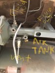
I cant really follow the tm legitimately due to the arrangement I have. The second air pack has an air line coming in straight from third tank. It then has one port plugged. Then the third port is the vent line that goes up to the t above driveshaft where the master vent and first airpack vent meet. Ill try to load up a decent pic with some labeling for review.deuceair2.jpg
 

jkcondrey

Active member
Steel Soldiers Supporter
317
141
43
Location
Rutherfordton, NC
I cant really follow the tm legitimately due to the arrangement I have. The second air pack has an air line coming in straight from third tank. It then has one port plugged. Then the third port is the vent line that goes up to the t above driveshaft where the master vent and first airpack vent meet. Ill try to load up a decent pic with some labeling for review. In the pic,
the other plugged port is out of view on the back side.

View attachment 754998
 

jkcondrey

Active member
Steel Soldiers Supporter
317
141
43
Location
Rutherfordton, NC
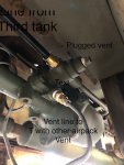
deuceair.jpegAnother view, text is not easy to see, but you can see the ports better. Black nylon goes back to tank. The smaller line is the current vent and you can see the plugged port.
 

jkcondrey

Active member
Steel Soldiers Supporter
317
141
43
Location
Rutherfordton, NC
PEASHOOTER: I cant make heads or tails of the tm attached to the brake line post. Do you know if the ports on the side all act the same, as in blow air constantly or only under braking as a pressure release? I am contemplating swapping the lines around on that ported side of the air pack to see if that is the issue. The tm does show the vent line being the lower port, that is the only definitive vent line seen in the tm. The initial diagram in the dual brake tm is pretty hard to follow with little detail. This almost makes me think that a glad hand line is swapped for the vent line, the only explanation I can come up with for the constant blowing of air out the vent.
 

tobyS

Well-known member
4,832
833
113
Location
IN
I've went front to back and back to front of this thread and a couple of other threads looking for the brake schematic of the M35A3....with no luck. I found several links that no longer work and come up with multiple threads when searching...still can't locate one. It sure would be easier if links didn't stop working on older threads. At the risk of repeating information that is located someplace, please post a brake schematic for the M35A3.
 

peashooter

Well-known member
1,038
205
63
Location
Hanover, minnesota
PEASHOOTER: I cant make heads or tails of the tm attached to the brake line post. Do you know if the ports on the side all act the same, as in blow air constantly or only under braking as a pressure release? I am contemplating swapping the lines around on that ported side of the air pack to see if that is the issue. The tm does show the vent line being the lower port, that is the only definitive vent line seen in the tm. The initial diagram in the dual brake tm is pretty hard to follow with little detail. This almost makes me think that a glad hand line is swapped for the vent line, the only explanation I can come up with for the constant blowing of air out the vent.
Download this TM for the m35a3:
https://www.steelsoldiers.com/upload/M35/TM9-2320-386-24P.pdf

I think most of what you need would be between pages 236-256, although it could still be unclear. If so let me know and I'll try to get some pictures under my truck for you. I cant remember off hand how much difference there is between the long and short air packs. Which ones do you have on your truck?
 
Top
AdBlock Detected

We get it, advertisements are annoying!

Sure, ad-blocking software does a great job at blocking ads, but it also blocks useful features of our website like our supporting vendors. Their ads help keep Steel Soldiers going. Please consider disabling your ad blockers for the site. Thanks!

I've Disabled AdBlock
No Thanks