• Steel Soldiers now has a few new forums, read more about it at: New Munitions Forums!

  • Microsoft MSN, Live, Hotmail, Outlook email users may not be receiving emails. We are working to resolve this issue. Please add support@steelsoldiers.com to your trusted contacts.

Deuce 4x4 with M105 reduced spring and air bag

tobyS

Well-known member
4,832
833
113
Location
IN
I've been posting on other threads like U-bolt and pinion angle so will bring the rear suspension to this thread, not piggyback on others.

The deuce frame is not cut (bobbed), but I am using an M105 bed (and springs) that will overhang the frame by 3". To center the wheel wells, the center of the axle is 50" from the end of the frame.

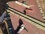
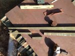
I'm plating the frame for 10' with an 11"x3" x 1/4" plate that makes the mount for the springs 3" below the 8" frame and widens the frame to 34 1/2".

I'm shooting for a height in the rear at the axle CL that is 3" higher than the front. Will have 165" wheel base.

The pinion angle appears to be about 6, 8, maybe 10 degree up with the 105 spring, and while pointing the driveshaft at the output of the transfer case, it is far from parallel. I made block for the perch assembly that reduces the angle by about 3 degree.

The M105 spring pack is a monster. It has 12 leafs and with no load, would probably not even move or make the shocks work. I want better ride than that gives. So I am reducing the springs, adding air bags and putting on 2 or 4 shocks.

Several threads deal with placement of shocks and end up with a large angle when they are outside of the frame connecting to the leaf spring. One thread had a comment about having 4 in a V shape that sounds interesting. I've decided that shocks will go inside of the frame and not be tied to the leaf spring perch, thus can hold off on fabricating them at this time and can concentrate on the leaf with air bag design.

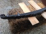
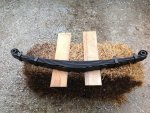
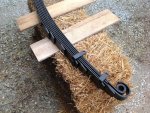
I have removed several leafs from the spring pack and am cleaning, beveling the ends, painting and will soon reassemble with anti-seize compound. I've taken 5 out.

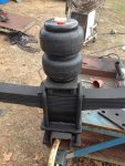
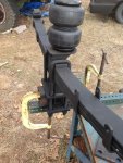
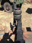
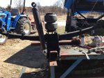
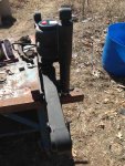
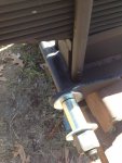
The air bag I'm using is a #2500 bag size, 6" dia and 7" when at max pressure with 7.7" of usable stroke. I'll round that off to about 4000 as far as load carrying as this bag says it is rated 2096#. I want to have 3/4" of clearance of the bag to frame, so had to offset the center of the bag away from the frame. My mount for the bag on the spring (below) is offset 3/4". The bag mount is then held on the top of the spring with the U-bolts. The springs are 2.5" wide and the bag mount uses a 2 1/4" x 1/2 (x 7 1/2") CR flat.

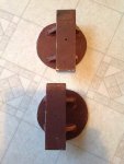
The photo shows a tapered steel material that I have, 2" thick and about 3 degree, I cut perch block from. After deciding to take additional leafs out, I cut a 6" piece off the thicker end and have these 1" to 1 1/4" blocks as surplus. I'll add photo's of more of these parts in the next couple posts.
 

Attachments

Last edited:

tobyS

Well-known member
4,832
833
113
Location
IN
I got the air bags yesterday and it's left me wondering what the mounting height should be. Specifications say it works from 2.8" height to 10.5", so 7.7" of travel. They recommend against making the bag hold the axle up but it is clear there must be both down movement and up movement.

How would one position the bag to have ample room for the axle to articulate down (with my 105 reduced spring) and have travel up? I've never mounted one and video's for mounting them focus on the "kits" with built in spacing. Should the bag have about equal down travel as up? Should I wait until the truck with bed is setting on the axle and springs with no load to position it?

The base of the bag needs about 4" diameter so the 6" diameter base above is going to be trimmed down a bit. Man, cleaning each leaf with dirt, grease and pockets of water/rust is a real PITA. What to use for lube when reassembling that won't hold dirt is another question? Wondering about aluminum paint between the layers instead of anti-seize.
 
Last edited:

Jbulach

Well-known member
Steel Soldiers Supporter
2,661
2,195
113
Location
Sunman Indiana
Do you have any pictures or links to the specs of your bags? Are they convoluted or rolling, and do they have bumpers? How much space do you have to wok with between top of your collapsed bag while sitting on the bottom mount and the bottom of the frame?
If you have plenty of freedom for you upper mounts vertical placement. I would wait until the axle is mounted, throw some simulated weight on the frame and do some articulation testing with a forklift or your crane.
 

tobyS

Well-known member
4,832
833
113
Location
IN
Off ebay. No bumpers that I know of. My M105 springs set beside the frame and I have plenty of room up and down. The offset keeps a 7" dia from rubbing on the side of the frame. Here is the title:

½"NPT SINGLE PORT CUSTOM SUSPENSION AIR SPRING/BAG/RIDE/SLAM DUAL PACK VXD2500DP

It is completely a guess, but about 3" down and 4" up. Yes, having springs on is probably the best.
 
Last edited:

tobyS

Well-known member
4,832
833
113
Location
IN
Here is one spring (near) complete. I added another leaf making it a 9 leaf pack. Each leaf was sanded with a sand pad on the grinder, red primer and black. I put a coat of aluminum paint on mating surfaces. I'm impressed with the precision of the shackles and pins and bearings...nice and scale right for the deuce. So 3 leafs removed. I still have to fix the clamps.
 

Attachments

Last edited:

gimpyrobb

dumpsterlandingfromorbit!
27,786
755
113
Location
Cincy Ohio
Sorry I'm late to see this. On another website, a guy used a paint called slip-plate on his spring pack which he said worked great.
 

tobyS

Well-known member
4,832
833
113
Location
IN
Thanks Chris, I have some "Lubri-Plate" someplace and a couple quarts of different size graphite that I used to experiment with but haven't seen recently.

The can of aluminum paint, about 1/3 full, had a huge amount of solid in the bottom from setting. When I mixed it up, it was like a thin Anti-seize. I put one together after painting it on and allowing it to set up and the layers were almost too slick to hang on to (slipped and all went flying). Maybe they won't stay that way, but given what I had with dirt, some rust (not excessive) and something that had dried rather hard, they have to be able to out-last me.

I noticed that all the ends had sharp edges... not any longer.
 

tobyS

Well-known member
4,832
833
113
Location
IN
Assuming my spring pack is typical M105A2, here is a little geometry of the spring. I think mine were close to new or mostly un-used, so not worn or stressed out.

It is 47" center of the pin to center of the pen and half that, 23.5" to the alignment bolt. All leafs are symmetrical, that I have encountered.

The frame mounts are also the same distance from the frame to the center of the pins, about 1 1/4".

The shackle from c to c is 3 1/2". Thus I can figure the angle at the axle mount (center) using a triangle that has 47" base and 3 1/2" end....= 4.17 degree. That is the angle of the mounting for an M105 spring and using parallel flat stock...not excessive at all.

My estimations were way off at 6-8-10*, but it is a welcome surprise because my 2.7 degree perch spacer now puts the angle of my pinion at just 1.5 degree from parallel. I'm real happy with that.
 
Last edited:

tobyS

Well-known member
4,832
833
113
Location
IN
My bags came, some machining will be done (large hole drilling) and the new U bolts should be here tomorrow. The second spring pack is together. I'm looking at the possibility of putting 2 or 4 shocks in a V that mount to the bag base on the outside of the frame now. My (2) shocks on hand are Monroe that were supposed to go on the front of my M929A2. They are probably larger than needed but I'm not sure that hurts. 4 seems way overkill but they are not too expensive....hmmmm

I'm about lost on how to calculate the load capacity, haven taken out 3 leafs from the 105 springs. What I have noticed is that the front springs of the M35A3 are the same width, 2.5", as the M105 spring, they are both 48" long, are symmetrical end to end and have the same number and thickness of leafs, 12 each. While I have not tried, it would appear the M105 spring could be interchanged with the front spring of the M35, only difference being the mounts, with the M35 front setting under the frame and the M105 mounted to the side. The main difference other than width being height from the spring pins to the frame.

I read where the M105 has a 10,000# rating on the axle. I don't know if that means the springs too. Since I am removing 3/12 of the leafs, I'll use 7,500# capacity and estimate my rear weight on the springs at 3,500#, leaving about 4,000# of spring capacity. With both air bags at 4000#, that should make a haul capacity of around 8,000#....well under the tire rating.

Feel free to make comments or correct my numbers for this combination.
 

tobyS

Well-known member
4,832
833
113
Location
IN
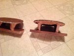
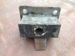
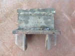
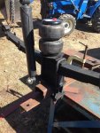
Here is a before cleanup photo of the saddle and perch welded up and the assembly with the air bag. The short square tube is 3 1/2", which is the same size as the axle housing. I don't know if I needed it for sure, but I put a weep hole through the big block so water that might go in around the bolt has a place to drain down.
 

Attachments

Last edited:

tobyS

Well-known member
4,832
833
113
Location
IN
I've found that the spring is 47" from center of pin to center of pin, not as I said earlier, 48". I measured on the M105 frame and the four mounting bolts are 46.5" center to center. It brings up the question, what if any angle should the shackle have? Should an unloaded spring have more than 90* so that when the spring flattens with the weight of the truck and then the weight of payload, it is supporting the weight at a right angle? As the spring flattens, it get's longer? It seems to suggest that with the weight of the truck on the spring, it should be at 90 degree and have room to move to 60 degree under heavy load.

There is a discrepancy between my measured distance on the M105 frame of 46 1/2" and the calculated distance on the frame mount. When I push down on the spring with the weight of the truck, the spring would be longer than 47", it would probably be 47.5" or more. For the shackle to be at 90 degree, the mount would have to be 47.5" apart, not less like the M105 has (at 46.5").

I'm preparing the frame plates and spring mounts and will confirm the positioning one more time. Any input on the shackle angle is appreciated...I kinda hate going against how the M105 has it. I'm going 47.5" unless someone talks me out of it.
 

tobyS

Well-known member
4,832
833
113
Location
IN
Most articles that deal with shackle angle are for off-road and a lot are working with jeeps that have front shackles. Also, many (dealing with rear suspensions) have the fixed end higher than the end that the shackle is mounted on. Ours is a straight frame.

In general, if the motion of the spring, for example lengthening under load, has to force the spring eye further away from the frame on the arc of the shackle pin, it is stiffer and has a higher spring rate. If the lengthening spring under load makes the shackle come closer to the frame, then the spring rate is reduced and a "softer" ride. At 90 degree to a line from pin to pin, the soft and higher rate is equal.

So a shackle that is vertical is not at 90 degree to the line from pin to pin. Earlier I calculated the spring angle at 4.17 (4.2) degree, pin to pin. If I put the shackle at fully vertical, 90 degree to the frame, I will be at about 85.8 degree to the spring centers. That will be "softer" ride, since the spring pin will move closer to the frame with any movement of the spring up (getting longer. I think one could go 10 degree and not feel that it is too soft.

So the bottom line for my build is that the spring will have a center to center estimated at 47.5" with only the weight of the truck on it. The shackle is 3.5" c to c. Using a right triangle calculator the distance apart for the spring mounts is 47.37" (or 47 3/8") to get the shackle at 90 to the frame with no payload.
 
Last edited:

tobyS

Well-known member
4,832
833
113
Location
IN
I got this from a member who was part of threads that came up on "shackle angle". He said;

"Want a better ride? Go more shackle angle, since you have the bags for towing.

10-15 degrees is ideal."

Plugging those numbers into the triangle calculator, using 105 degree, the length becomes 46.47". Using 100 degree the distance is 46.77". I will use 46 5/8" (46.625).

Now we are getting close to the measured distance on the M105 of 46.5"....and it is making more sense.
 
Last edited:

tobyS

Well-known member
4,832
833
113
Location
IN
I think your right on track.
I have put 8k lb in a m105 and it just sits on the secondary springs.
That is about 3" of travel, right? Having 3 leafs of 12 taken out, I don't think I've reduced the capacity more than 25%, if that. I would think a 6,000+ payload to have about the same amount of travel. Then 4000# on the bags, so should do 10K or so. Seems that will pull a nice size gooseneck trailer (ball says 17,000 trailer gvw).

I've always had two aversions to making the deuce into a distance or vacation ride.... the slow speed and the rough ride. I may have to reconsider that a bit if the ride quality is very much improved.

Porkysplace made a suggestion that is growing on me...a sleeper. I have about 32" between the M105 bed and the back of the cab.
 
Top
AdBlock Detected

We get it, advertisements are annoying!

Sure, ad-blocking software does a great job at blocking ads, but it also blocks useful features of our website like our supporting vendors. Their ads help keep Steel Soldiers going. Please consider disabling your ad blockers for the site. Thanks!

I've Disabled AdBlock
No Thanks