• Steel Soldiers now has a few new forums, read more about it at: New Munitions Forums!

  • Microsoft MSN, Live, Hotmail, Outlook email users may not be receiving emails. We are working to resolve this issue. Please add support@steelsoldiers.com to your trusted contacts.

Mep 002a voltage

Chainbreaker

Well-known member
1,796
1,992
113
Location
Oregon
If you haven't already you need to download the Technical Manuals for your unit and become familiar with them. You can find detailed illustrations, schematics with terminal #'s, part #'s, etc. for the items you are troubleshooting.

At the top of this thread select > "Home" and then under the > "Technical Manuals" section you will find all the TM's for the MEP-002a.
 

Ray70

Well-known member
2,592
5,907
113
Location
West greenwich/RI
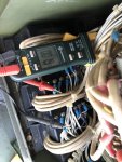
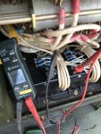
The 2 big black things with the holes and the main AC wires looped through it are CT1 and CVT1
The one closest to you is the CVT1, the one behind is the CT1
You need to disconnect the small wires by removing the screws and test per the TM and see how your resistance readings compare.
Don't be overly alarmed if you see a small difference because you might have a little added resistance in your meter and leads, unless you can zero it out. If you are off substantially, that would be a problem.
 

Guyfang

Moderator
Staff member
Moderator
16,763
24,068
113
Location
Burgkunstadt, Germany
Take your time removing the nuts that hold the wires on. Sometimes its not a bad idea to spray them a tad with WD-40 or something like that. Give it a chance to work. I have broken off several, more then several, of the connections I started using penetrating oil.
 

RJM27

Active member
359
30
28
Location
Burdett NY
Take your time removing the nuts that hold the wires on. Sometimes its not a bad idea to spray them a tad with WD-40 or something like that. Give it a chance to work. I have broken off several, more then several, of the connections I started using penetrating oil.
Will do, have plenty of PB blaster, let it soak. Thanks
 

Triple Jim

Well-known member
1,375
287
83
Location
North Carolina
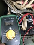
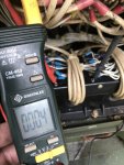
If you mean 2.0 ohms, that's a problem. Check the "-34" TM, but as I remember that resistance should be 9.6 ohms plus or minus 0.96 ohms.
 

Triple Jim

Well-known member
1,375
287
83
Location
North Carolina
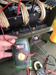
That photo shows you measuring the resistance at the wires. You need to measure it on the C1 and C2 terminals on the transformer. You're checking the transformer winding.
 

RJM27

Active member
359
30
28
Location
Burdett NY
Thanks, it’s probably karma for areas where I get it and can’t understand why others struggle! Not easy being easy! You guys have always come through & made it happen! BTW Happy Mother’s Day 😎
 

Triple Jim

Well-known member
1,375
287
83
Location
North Carolina
I just went out to my MEP-003A and looked. You're on CT1. CVT1 is the one that's away from where you're sitting when you look at the pair. CT1 should have "CT1" molded into the housing facing you. That's the wrong one.

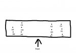
Put those wires back on and find C1 and C2 on CVT1. I found a diagram someone drew that shows the terminals. Locate screw terminals C1 and C2 and verify you have the correct terminals by finding the markings near them, molded into the plastic. Remove the wire from one of them and measure the resistance between those two screw terminals on the transformer. You may have to remove the wires from both of the terminals so you can see the "C1" and "C2" molded into the plastic, therefore indicating you have the correct ones.

CVT1.jpg
 
Last edited:

RJM27

Active member
359
30
28
Location
Burdett NY
I just went out to my MEP-003A and looked. You're on CT1. CVT1 is the one that's away from where you're sitting when you look at the pair. CT1 should have "CT1" molded into the housing facing you. That's the wrong one.

Put those wires back on and find C1 and C2 on CVT1. I found a diagram someone drew that shows the terminals. Locate screw terminals C1 and C2 and verify you have the correct terminals by finding the markings near them, molded into the plastic. Remove the wire from one of them and measure the resistance between those two screw terminals on the transformer. You may have to remove the wires from both of the terminals so you can see the "C1" and "C2" molded into the plastic, therefore indicating you have the correct ones.

View attachment 799448
Meter set on 200
 

Attachments

Top
AdBlock Detected

We get it, advertisements are annoying!

Sure, ad-blocking software does a great job at blocking ads, but it also blocks useful features of our website like our supporting vendors. Their ads help keep Steel Soldiers going. Please consider disabling your ad blockers for the site. Thanks!

I've Disabled AdBlock
No Thanks