• Steel Soldiers now has a few new forums, read more about it at: New Munitions Forums!

  • Microsoft MSN, Live, Hotmail, Outlook email users may not be receiving emails. We are working to resolve this issue. Please add support@steelsoldiers.com to your trusted contacts.

MEP-002A Left Connected when Main Power was Restored

To properly test a diode, at least one side/wire of the diode/circuit has to be separated from the circuit. Both sides is what I always tried to do. But at least one side. Read the directions on your tester. If something is not clear, give a shout. Oh, and dont forget to look at the back side of the card.
I did not see this reply before I went out to test the diodes so i tested them on the board. According to my Klein CL800 manual a reading of OL in both directions indicates an open device. That is what I get. I do not get any reading on any of the diodes at all (200-800mv would be typical per the manual), they all read OL.

I tested the resistor and it reads at 55.1 Ohms.
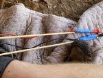
It was really frustrating trying to get two hands and both probes into the back of the cabinet and reliably place the probe tips and read the meter, so was feeling so clever for devising a way to get the probes into the back of the cabinet without my hands getting all in the way (see pictures). Do I need to remove the board from the cabinet and test on a bench? Obviously I can’t see the back of the board with it still in cabinet.
 

Attachments

I know its a PITA, but you can not test the diodes in the set.
You are absolutely correct. I pulled the board and had to pierce the conformal/epoxy coating to get a reading on the diodes, and they were correctly biased and read between .54-.55 V(**) on all 6. Resistor still measures ~55 Ohms. I put new conformal coating over the locations where I pushed through it for the measurements and have it reinstalled back in the cabinet with the terminals reconnected.

***Edit-my original reply here erroneously stated .55 V in stead of .55 Ohms
** Edit 2 My original value of ~.55 V drop across the diodes was correct
 
Last edited:

cuad4u

Active member
268
88
28
Location
St Matthews, SC
I am no expert but I am an electrical engineer. I have made a life time hobby of restoring HAM radios and old broadcast and shortwave radios. A good silicon diode will show around 0.6 ohms in one position and near infinite resistance in the other position. The best way to test the diodes is to unsolder one leg of the diode and test both positions. Some older diodes look like your picture. Most are a cylinder.
 
I am no expert but I am an electrical engineer. I have made a life time hobby of restoring HAM radios and old broadcast and shortwave radios. A good silicon diode will show around 0.6 ohms in one position and near infinite resistance in the other position. The best way to test the diodes is to unsolder one leg of the diode and test both positions. Some older diodes look like your picture. Most are a cylinder.
Good catch! I apologize, I should have stated .55 Ohms, not Volts. So i think that the .55 Ohms i was getting is close to your stated average of around .6 Ohms. I've corrected the post above.
 
Last edited:
Roger. That looks good. Now you want to hook up the cable. Then find TB3-5 and TB3-6. You want to mesure between those two terminals, on start up. You need to see 24 volts DC there.
Ok, first thanks for sticking with me this far. Second, i need to back up a step, i did not check those two terminals at TB3 for 24V "ON STARTUP". I misunderstood what you meant and was checking them with the generator STARTED and running. My apologies. So I came back out and tested again at TB3-5 and TB3-6 reading only while S1 was engaging all the way to the “Start” position and I do not get 115 mV. I also still do not get 24V, I get around 8-9 VDC. It may be hitting 24 VDC it i cant see it because it’s happening too fast and it’s auto-ranging, but it seems to settle at 8-9 V after about 1 second. I’m not sure what that means but there it is. Where do I go after the A4 board trying to find this 24 VDC?
 

Triple Jim

Well-known member
1,376
292
83
Location
North Carolina
Good catch! I apologize, I should have stated .55 Ohms, not Volts. So i think that the .55 Ohms i was getting is close to your stated average of around .6 Ohms. I've corrected the post above.
You were correct before. The diode test function of the meter applies a small current to the diode and measures the voltage drop across its junction. Then it displays that forward voltage drop.

Resistance of the junction is not something that's useful to try to measure, since the apparent resistance will vary with the amount of current passed through it during the measurement.
Ok, well, i guess at this point all i know is that i was in the Diode test mode, and that i was getting a number of around .54-.56 [some unit here] on the multimeter screen, and that when i reversed the probes i was getting OL. Several of the circuit traces were linked, but i did get different numbers each time i moved the probes to either side of the closest diode. When i removed the circuit board, i did not see any traces of over heating or burnign at all. Boiling down the facts to the final question, are these diodes and resistor on the A4 likely good? If so, where do i go next?
 

Triple Jim

Well-known member
1,376
292
83
Location
North Carolina
Ok, well, i guess at this point all i know is that i was in the Diode test mode, and that i was getting a number of around .54-.56 [some unit here] on the multimeter screen
The manual to your meter should explain that the displayed number is the forward voltage drop of the diode.

Here is an excerpt from the Fluke 87 manual:

"Use the diode test to check diodes, transistors, silicon controlled rectifiers (SCRs), and other semiconductor devices. This function tests a semiconductor junction by sending a current through the junction, then measuring the junction's voltage drop. A good silicon junction drops between 0.5 V and 0.8 V. "
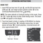
Yes, i guess i shouldn't have doubted myself. The reading i got was a voltage drop across the diode. Attached is the picture from my manual for the diode test function.
 

Attachments

Triple Jim

Well-known member
1,376
292
83
Location
North Carolina
I also still do not get 24V, I get around 8-9 VDC. It may be hitting 24 VDC it i cant see it because it’s happening too fast and it’s auto-ranging, but it seems to settle at 8-9 V after about 1 second. I’m not sure what that means but there it is. Where do I go after the A4 board trying to find this 24 VDC?
It's normal that the exciter voltage is less than 24. That resistor on the A4 board is there to drop the 24v to a lower value, limiting the current. I just started my 003A and measured the exciter voltage during cranking and when the engine started. It was less than 9v during cranking, and momentarily went to about 24 when the engine began to run and the starter disengaged. This was while the engine was not up to speed and the regulator was allowing full voltage from CVT1 through A4 to get to the exciter. When everything settled down it was steady at slightly under 12VDC.
 
It's normal that the exciter voltage is less than 24. That resistor on the A4 board is there to drop the 24v to a lower value, limiting the current. I just started my 003A and measured the exciter voltage during cranking and when the engine started. It was less than 9v during cranking, and momentarily went to about 24 when the engine began to run and the starter disengaged. This was while the engine was not up to speed and the regulator was allowing full voltage from CVT1 through A4 to get to the exciter. When everything settled down it was steady at slightly under 12VDC.
Ahh ok. So I’m not sure where to go next in looking for the problem. Any ideas?
 
In the -34 TM are instructions on how to test. Open the -34 and go to PDF reader page #150 and start reading.
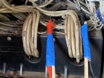
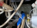
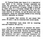
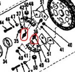
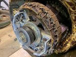
I think my PDF pages numbers are slightly different, but on my page 149, Section II, 8-2, 3a, b, c and notes state the attached. I pulled the cover off and started looking for the diodes and took pictures of the diodes on the unit, and then i came back in and referred back to the manual to get an idea of exactly what i should be looking for. When i was looking at the generator i was thinking that i was seeing at least 3 and possibly 4 diodes on each side of the exciter for a total of 6-8, but it appears that in the manual there are only 2? These are what i *think are the diodes indicated by arrows in the pictures from the genset. How many diodes are there supposed to be? So far the easiest way to do this seems to be to reach under the upper cabinet towards the end of the genset. What do i do for the diodes that are hidden behind the end casting of the genset that I can't reach? Would turning S1 to bump the starter until i could reach and test each one, marking the ones i tested as good and bad (if any) work or is there a better method of reaching each one?
 

Attachments

Triple Jim

Well-known member
1,376
292
83
Location
North Carolina
It's been a while since I looked at mine, but I think there are two heat sinks, each with three diodes on it. Look around the full circle. There are three of each of two types. One type is cathode on the threaded stud and the other type is anode on the threaded stud.

Here's some information from an old post I made:
"After doing a little research for David, I found that while the 1N1204A and 1N1204RA are in short supply, their 600v counterparts are not. The 1N1206A and 1N1206RA are in stock at several suppliers, Mouser being one, for about $6 each."
 

Guyfang

Moderator
Staff member
Moderator
16,793
24,144
113
Location
Burgkunstadt, Germany
I think my PDF pages numbers are slightly different, but on my page 149, Section II, 8-2, 3a, b, c and notes state the attached. I pulled the cover off and started looking for the diodes and took pictures of the diodes on the unit, and then i came back in and referred back to the manual to get an idea of exactly what i should be looking for. When i was looking at the generator i was thinking that i was seeing at least 3 and possibly 4 diodes on each side of the exciter for a total of 6-8, but it appears that in the manual there are only 2? These are what i *think are the diodes indicated by arrows in the pictures from the genset. How many diodes are there supposed to be?

(An easy way to find out how many ANYTHING is in a set, is by looking at the -24P. For instance, the diodes. Look them up in the -24P, and you find only two diodes in the drawing with an item number. What you are looking at is one of each type diode. No need to list them all. When you look at the item description, almost all the way to the right, is a field for how many are in that figure you are looking at, (in this case 3) and the next field over shows how many total in the entire gen set, (in this case 3). That's one way. So, that means there are 3 of each kind. Total of 6. Do not mix them up. I am the kind of guy that would simply buy 6 new diodes and put them in. After all the work of getting at them, I figure its cheap insurance. Use a GOOD soldering iron. Good paste. Do not over heat them. If you just want to test, and this is the best way, un-solder them. Remove them from the heat sink. Test them, (or simply replace them) and then re-solder them to the wire.

So far the easiest way to do this seems to be to reach under the upper cabinet towards the end of the genset. What do i do for the diodes that are hidden behind the end casting of the genset that I can't reach? Would turning S1 to bump the starter until i could reach and test each one, marking the ones i tested as good and bad (if any) or is there a better method of reaching each one? (This is a way, yes. I have a small scar in my arm, from doing something very much like this. Someone who went straight to the top of my NO Christmas card list, turned on the start switch. So if you do it this way, I would unhook the main neg. battery terminal before sticking my fingers in there. Or work alone. Trust is a wonderful thing. Rare, but wonderful.
I would remove the Neg battery terminal, the remove the safety cover that allows you to remove the bolts that couple the main gen to the engine. After removing the cover, I use a pry bar to carefully move the cooling fins, and turn the main gen.

My preferred method is to simply remove the main gen end cover. Your picture shows me a main gen that has seen many years of service. Some cleaning would not hurt.
Open to read comments.
 
Open to read comments.
That’s a great picture and helps clear up a few things for sure! To use your preferred method of removing those main bolts coupling the main gen end cover, does that require me to support that end bearing in any way or is it ok cantilevered like that just for the static tests we are talking about?

What’s the best way to clean it? Should I spray everythingi can see with some kind if preservation oil or WD-40? I don’t think scrubbing with a wire brush is what I’m after 😁, but I don’t think just wiping things down will do either. Thanks again.
 
Top
AdBlock Detected

We get it, advertisements are annoying!

Sure, ad-blocking software does a great job at blocking ads, but it also blocks useful features of our website like our supporting vendors. Their ads help keep Steel Soldiers going. Please consider disabling your ad blockers for the site. Thanks!

I've Disabled AdBlock
No Thanks