• Steel Soldiers now has a few new forums, read more about it at: New Munitions Forums!

  • Microsoft MSN, Live, Hotmail, Outlook email users may not be receiving emails. We are working to resolve this issue. Please add support@steelsoldiers.com to your trusted contacts.

M1078 Circuit Breaker Schematic/ The Quest For

Lugnuts

Active member
Steel Soldiers Supporter
323
239
43
Location
Myakka City, FL
Maybe senility has set in and the powers of observation have dwindled but I cannot find in all the manuals a schematic for the circuit breakers (looking especially for CB65) depicting where the power comes from and where it goes to. I'm sure its somewhere. Please somebody prove me an idiot and I will be most grateful. Thank you, Lugnuts
 

Mullaney

Well-known member
Steel Soldiers Supporter
Supporting Vendor
7,716
19,766
113
Location
Charlotte NC
Maybe senility has set in and the powers of observation have dwindled but I cannot find in all the manuals a schematic for the circuit breakers (looking especially for CB65) depicting where the power comes from and where it goes to. I'm sure its somewhere. Please somebody prove me an idiot and I will be most grateful. Thank you, Lugnuts
.
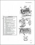
I keep hearing that there is a 30ft long drawing of the entire electrical system in these S&S trucks. I personally have not ever found that, but I did find a picture of where it is and possibly how to troubleshoot?

TM 9-2320-366-366-20-1 CB65.jpg
 

Mullaney

Well-known member
Steel Soldiers Supporter
Supporting Vendor
7,716
19,766
113
Location
Charlotte NC
its in the back of TM xxxx 20-1 TM starting page 1653
Wow!!!! It really does exist!

In my version of the book it is a few pages further back (Page 1719) but I found it.
Thanks coachgeo ! I really do appreciate it.

Maybe the difference is MTV vs LMTV or my book just has more "fluff" in it than yours.
 

Ronmar

Well-known member
3,846
7,475
113
Location
Port angeles wa
It is in the back of all the tech manuals, right in front of the change request form...

yes, it is a bunch of pages designed to go end to end so is over 30’ long when printed on 8.5X11 paper and assembled.

CB 65 is the park light fuse, it is electrically located between the main light switch and the front bumper lighting connector...
 

Lugnuts

Active member
Steel Soldiers Supporter
323
239
43
Location
Myakka City, FL
.
I keep hearing that there is a 30ft long drawing of the entire electrical system in these S&S trucks. I personally have not ever found that, but I did find a picture of where it is and possibly how to troubleshoot?

View attachment 830648
Thank you all for the information and willingness so impart that information !
Any input on my senility and powers of observation?
Lugnuts
 

Mullaney

Well-known member
Steel Soldiers Supporter
Supporting Vendor
7,716
19,766
113
Location
Charlotte NC
Thank you all for the information and willingness so impart that information !
Any input on my senility and powers of observation?
Lugnuts
.
I don't think so unless both of us have that same "lack of observation" skill set. :)
I had been hearing about that thirty foot long drawing for a while.

A search in TM-9-2320-366-20-1 did not find "CB65" anywhere in that drawing.
Who knows, maybe later I will find it with a dash or a space . . .

----

As for the senility part of the equation, there may be some benefit to it:
This time of the year specifically: If you find yourself to be in a "senile situation"
you can always hide your own easter eggs... All in how you look at it I guess.
 

B-Dog

Well-known member
164
289
63
Location
Denver, CO
A search in TM-9-2320-366-20-1 did not find "CB65" anywhere in that drawing.
Who knows, maybe later I will find it with a dash or a space . . .
Check page 1741, or at least that's where it's at on my PDF of that TM part number. It should be 'foldout 17/40" in any of the manuals It would behoove anyone who wants to troubleshoot electrical in these rigs to familiarize one's self with the grid system. Look at the numbers at the bottom of the schematic for 150 and the letter on the side, D. This would be called out, D150 in other parts of the schematic. There you will find CB65 for the parking lights :)
To answer your original question, 12v goes through CB 70, to the light switch, then via wire 491, goes to CB65, then to the front Right and Left parking lights in the turn signal housing.


1618103558191.png
 
Top
AdBlock Detected

We get it, advertisements are annoying!

Sure, ad-blocking software does a great job at blocking ads, but it also blocks useful features of our website like our supporting vendors. Their ads help keep Steel Soldiers going. Please consider disabling your ad blockers for the site. Thanks!

I've Disabled AdBlock
No Thanks