• Steel Soldiers now has a few new forums, read more about it at: New Munitions Forums!

  • Microsoft MSN, Live, Hotmail, Outlook email users may not be receiving emails. We are working to resolve this issue. Please add support@steelsoldiers.com to your trusted contacts.

FLU419 Hydraulic Cooling Fan Service

glcaines

Well-known member
3,914
2,594
113
Location
Hiawassee, Georgia
Has anyone successfully dismantled a hydraulic cooling fan motor and serviced it successfully? Of the two fans on my FLU, one spins freely and the other will barely turn when I spin them manually. I have not tried to put 24 VDC to them to actually test them yet. Most of my excavation work with the SEE has been in very cold weather and the hydraulic oil hasn't gotten hot enough for the fans to turn on automatically. My next step is to provide 24 VDC to each motor to see whether they run, or try to run and I'll go from there. However, the very stiff one obviously needs help.
 

peakbagger

Well-known member
734
360
63
Location
northern nh
I autopsied one that was real stiff. Its a known problem that is covered by a service advisory. The grommets feeding power into the can were mounted facing up and dry rotted from sunshine letting water inside. The military fix was gob it up with silicone. The interior was pretty badly rotted. I ended up buying some SPAL brand fans on Ebay and building an adapter plate. I posted details long ago. My guess is trying to fix what you have has a low likelyhood of success. I have the old ones stashed away.

BTW if you pull too much load on the circuit, its the big red fuse on the left side of the right side fusebox. (when standing in front of SEE). The fuse only blows when the hydraulic temperature switch clicks on. You can test it all from the terminal panel at the base of the cooling fan case. The electrical diagnosis section of the manuals have the wiring diagram (I dont think its on the SEE diagram).

In warm temps (70) degrees they cycle on and off, they pretty well ran constantly when digging on 80 degree this summer when I was ripping at ledge with my ledge bucket. (military option).
 
Last edited:

glcaines

Well-known member
3,914
2,594
113
Location
Hiawassee, Georgia
Thanks for the reply. I've been digging with my SEE quite a bit, but mostly when the temperature was around 25 - 35 deg. F. I checked all of my fuses, and the one you mentioned isn't blown. Actually, none of my fuses were blown, but several don't make good contact with the fuse holder. I ordered all new fuses since my old fuses are well oxidized on the contacts. I'm going to take my dremel tool with a brass brush and try to polish up the contacts in the fuse holders so the new fuses make good contact. I spun all of the fuses around to improve contact, and now my horn works. I'm going to remove the stiff fan motor and dismantle it and see what the insides look like. I'm sure the inside will look like what you found. I suspect that the fan that still spins freely might work when I put 24 VDC to it. If the other fan motor works, I'll seal the wires with silicone as you suggested.
 

The FLU farm

Well-known member
Steel Soldiers Supporter
3,342
1,328
113
Location
The actual midwest, NM.
You can check function by bridging the sensor on top of the cooler. My fans very rarely run, except when using the snowblower, but one did die on the Winter SEE.
Stupidly stole one from the Summer SEE (which was supposed to be a parts car), so I ended up getting a close copy - off of eBay, I think - to replace it with.
You could also wire two easier to find 12 V fans in series, but then there will be nothing if one craps out.
 

Brents347

New member
27
14
3
Location
Truckee, CA.
As a quick follow up to this, when replacing my fans and going through the hydro cooling system I found that there are TWO temps sensors on the system to trigger the fans. One is on the top of the cooler under one of the little corner covers, and the other is on the bottom of the cooler on the same side. It is impossible to get to without completely removing the oil cooler from the truck, so that is what I did. My wiring was also a bit of a mess (and the wiring schematic doesn’t cover the Freightliner add-ons) so I wired my fans so that one sensor triggers each fan. It seems to me that with two sensors, one top and one bottom, one must be the incoming oil line and the other the outgoing oil line. So the way I have it wired now, when the incoming oil is hot it triggers one fan, and when the oil is STILL hot leaving the cooler then it triggers the other fan. I don’t know, it works in my head.
 

peakbagger

Well-known member
734
360
63
Location
northern nh
As a quick follow up to this, when replacing my fans and going through the hydro cooling system I found that there are TWO temps sensors on the system to trigger the fans. One is on the top of the cooler under one of the little corner covers, and the other is on the bottom of the cooler on the same side. It is impossible to get to without completely removing the oil cooler from the truck, so that is what I did. My wiring was also a bit of a mess (and the wiring schematic doesn’t cover the Freightliner add-ons) so I wired my fans so that one sensor triggers each fan. It seems to me that with two sensors, one top and one bottom, one must be the incoming oil line and the other the outgoing oil line. So the way I have it wired now, when the incoming oil is hot it triggers one fan, and when the oil is STILL hot leaving the cooler then it triggers the other fan. I don’t know, it works in my head.
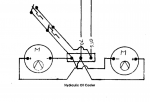
FYI, the student handout that is stored in the Misc Tech manuals has the wiring diagram for the back platform. Here is snip from the cooler. Looks like the switches are in parallel so if one is not working the second one works to turn on the fans.

Here is a link to the manuals https://www.steelsoldiers.com/threa...flu-419-manuals-and-a-student-handout.170940/
Note the version of the overall wiring diagram in the handout is not great, there better scan in another thread in that forum.

1623663989095.png
 
Last edited:

Speedwoble

Well-known member
606
301
63
Location
New Holland, PA
Is it more likely that one switch is in the back hydraulic circuit and one is in the front hydraulic circuit? It has been a while since I looked at it, but I think both circuits run through the cooler.
 
Top
AdBlock Detected

We get it, advertisements are annoying!

Sure, ad-blocking software does a great job at blocking ads, but it also blocks useful features of our website like our supporting vendors. Their ads help keep Steel Soldiers going. Please consider disabling your ad blockers for the site. Thanks!

I've Disabled AdBlock
No Thanks