• Steel Soldiers now has a few new forums, read more about it at: New Munitions Forums!

  • Microsoft MSN, Live, Hotmail, Outlook email users may not be receiving emails. We are working to resolve this issue. Please add support@steelsoldiers.com to your trusted contacts.

MEP-804A Diode Ring Destroyed

peapvp

Well-known member
Steel Soldiers Supporter
1,113
1,229
113
Location
Basehor, KS
It's hard to tell since there isn't any history that came with the set. The one thing that we do know is that the failed assembly wasn't made by Marathon Electric. They confirmed that it didn't carry their markings. Another member, @FLCarguy, posted a similar failure suggesting that it may be common to the mystery diode ring. It's all supposition at this point in time, but the more members, like you and @FLCarguy, who report in, the better our understanding will become.
Since this is not a Marathon product, I would say it was procured from the lowest bidder who overhauled the gensets under contract.

I am sure this bidder did not have these diode rings manufactured by a union shop, a class of 6th graders in Wisconsin or any reputable US shop who could produce this type of part.

The child labor wages in this country are just to astronomical, never mind commercial shop rates………..
 

peapvp

Well-known member
Steel Soldiers Supporter
1,113
1,229
113
Location
Basehor, KS
I ordered a diode ring from Marathon Electric. I felt that if I was going to go through all of this work, I may as well give myself the best chance of diode ring survival. With that said, we don't know why DOD sourced it elsewhere. It may well be that the OEM part was the lemon. But... it feels more solid in my hand than the alternate source assembly. I now have three assemblies: 1) self-destructed, 2) one attached to the replacement rotor, and 3) OEM replacement. OEM stands for Original Equipment Manufacturer. I noticed something that may have no bearing on the self-destruct mode, but the non-OEM assemblies are mounted on a composite ring, presumably fiberglass. The edge is rather rough suggesting that it was sawn rather than die cut. Also, the rivets, what we assumed were the failure mode (read above), appear to be better swaged on the OEM assembly (edges rolled over).

View attachment 882403

View attachment 882404


Swaged edge of rivets not as beefy as OEM part. We suspect that the rivet was the failure mode that caused the ring to break apart.
View attachment 882405

Swaged edge of rivets not as beefy as OEM part. We suspect that the rivet was the failure mode that caused the ring to break apart.
View attachment 882406

Nice clean edge suggests die cut
View attachment 882407

The rough edge suggests the ring was sawed instead of die cut. Of course, it could have gotten roughed up when it broke apart, but if we compare it to the replacement rotor's diode ring they look similar. It's not possible to say that the broken diode ring and the replacement rotor's diode ring were made by the same manufacturer.
View attachment 882408

This photo was taken of the replacement rotor. I can't yet remove the diode ring because I have to pull the bearing at the end of the shaft. The bearing is supporting the rotor in a wood cradle at the moment so pulling it now would be bad timing.
View attachment 882410
Evvy,

I have been around the block a couple of times.
When you take out the bearings to change the diode ring, examine the bearing very very closely.
If it is of questionable origin, replace the Bearing with a high grade NSK, SKF etc Bearing.
The fleecing of American Tax Dollars…..

3889920C-EBC4-43B6-9BEC-D85158A9EFA2.jpeg
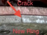
Picture of the diode ring on the new generator head you just bought and which you are replacing with the OEM Marathon Diode Ring
 

Evvy Fesler

Well-known member
366
772
93
Location
Roxboro, North Carolina USA
Evvy,

I have been around the block a couple of times.
When you take out the bearings to change the diode ring, examine the bearing very very closely.
If it is of questionable origin, replace the Bearing with a high grade NSK, SKF etc Bearing.
The fleecing of American Tax Dollars…..

View attachment 882460
Picture of the diode ring on the new generator head you just bought and which you are replacing with the OEM Marathon Diode Ring
Thanks, Peter! I read in the TM that the bearing should be replaced every time you remove it (remove and discard) so I bought a new SKF for $28 USD. Cheap assurance. Good catch on the crack in the so called new diode ring on the replacement rotor. I don't want to misrepresent that generator head though. I have no illusions that it's new. I bought it on auction from Ritchie Brothers in Las Vegas. That's why I'm replacing its diode ring.

Readers... heads up! The picture labeled "New Ring" above isn't the brand new OEM diode ring. It's a picture of the diode ring on the auctioned "new to me" rotor.
 
Last edited:

Ray70

Well-known member
2,592
5,907
113
Location
West greenwich/RI
To comment on 87cr250r's Overspeed question, while ANYTHING is possible with these generators, I believe that machine does have over speed safety's but in addition, I would suspect that a correctly manufactured diode ring would be able to handle much more "overspeed" than the engine's internals could.
In other words I'd expect to see "external" connecting rods long before an exploded diode ring....
 

87cr250r

Well-known member
1,267
1,988
113
Location
Rodeo, Ca
I'm not a military guy, I just have a CUCV. I do operate a fleet of tug boats with 99-150KW generator sets. I have non-specific experience. The rectifier rings should easily tolerate 1800 and 3600 rpm conditions. What rpm do these MEP sets operate at? I've been assuming 1800 like most commercial sets.
 

Evvy Fesler

Well-known member
366
772
93
Location
Roxboro, North Carolina USA
I'm not a military guy, I just have a CUCV. I do operate a fleet of tug boats with 99-150KW generator sets. I have non-specific experience. The rectifier rings should easily tolerate 1800 and 3600 rpm conditions. What rpm do these MEP sets operate at? I've been assuming 1800 like most commercial sets.
Good morning @87cr250r ! Yes, 1800
RPM. You’ve piqued my curiosity! What do you use the generators for on a tug boat?
 

87cr250r

Well-known member
1,267
1,988
113
Location
Rodeo, Ca
Generators are used for typically hotel stuffs such as lights and air conditioning. There are also a few pumps. Our sets are large because they also provide power for the winches. Our boats have 75 horsepower electric winches and up to 100 horsepower hydraulic winches.
 

Evvy Fesler

Well-known member
366
772
93
Location
Roxboro, North Carolina USA
Generators are used for typically hotel stuffs such as lights and air conditioning. There are also a few pumps. Our sets are large because they also provide power for the winches. Our boats have 75 horsepower electric winches and up to 100 horsepower hydraulic winches.
Wow! That’s fascinating. Thank you for sharing. Maybe we’ll get to see your operation the next time we travel out to the West Coast.

Evvy-
 

Guyfang

Moderator
Staff member
Moderator
16,766
24,075
113
Location
Burgkunstadt, Germany
To comment on 87cr250r's Overspeed question, while ANYTHING is possible with these generators, I believe that machine does have over speed safety's (4. OVERSPEED indicator Lights when engine speed exceeds 2200±40 RPM.) but in addition, I would suspect that a correctly manufactured diode ring would be able to handle much more "overspeed" than the engine's internals could.
In other words I'd expect to see "external" connecting rods long before an exploded diode ring....
 

Evvy Fesler

Well-known member
366
772
93
Location
Roxboro, North Carolina USA
An update... making progress on getting the old generator out of the genset. Many of you will no doubt be pleased that I did indeed expand my vocabulary!

I need some ideas about how to remove the big bolts that fasten the generator to the skid. Tugging on a breaker bard was futile. My impact wrench doesn't fit under the curvature of the stator housing. Maybe a universal... also thinking of using a LAP to extend the breaker bar. What are your ideas? What's the purpose of the bolt with the lock nut (on the right in this pic)? Is it some sort of jack to make sure the mounting bolt stays in place?

A1ED5B5E-B669-455F-A29C-4FC1268778B7.jpeg
 
Last edited:

Mullaney

Well-known member
Steel Soldiers Supporter
Supporting Vendor
7,716
19,766
113
Location
Charlotte NC
An update... making progress on getting the old generator out of the genset. Many of you will no doubt be pleased that I did indeed expand my vocabulary!

I need some ideas about how to remove the big bolts that fasten the generator to the skid. Tugging on a breaker bard was futile. My impact wrench doesn't fit under the curvature of the stator housing. Maybe a universal... also thinking of using a LAP to extend the breaker bar. What are your ideas? What's the purpose of the bolt with the lock nut (on the right in this pic)? Is it some sort of jack to make sure the mounting bolt stays in place?

View attachment 883459
.
I would guess that long bolt with the jam nut was whatever whomever had and just "made it work".
 

Guyfang

Moderator
Staff member
Moderator
16,766
24,075
113
Location
Burgkunstadt, Germany
An update... making progress on getting the old generator out of the genset. Many of you will no doubt be pleased that I did indeed expand my vocabulary!

I need some ideas about how to remove the big bolts that fasten the generator to the skid. Tugging on a breaker bard was futile. My impact wrench doesn't fit under the curvature of the stator housing. Maybe a universal... also thinking of using a LAP to extend the breaker bar. What are your ideas? What's the purpose of the bolt with the lock nut (on the right in this pic)? Is it some sort of jack to make sure the mounting bolt stays in place?

View attachment 883459
Long bolt on the right side is there to prop up the main gen, when you do the engine removal. You can put a block of wood or something metal under it, turn the bolt down and support the main gen. Look at it. If you pulled just the engine, the main gen would topple forwards.

I would use heat ON TOP of the mounting bolt. On the bottom, you will melt the Rubber Baby Bumper. Heat it up a bit, let it cool. Heat it up a bit, let it cool. Then use a penetrating oil, on the bolt and threads. Let it sit. I would apply it just before Miller time, and then let it stand over night. If you can wack it a good one with a hammer, (Hard, I know) that often helps. And yes, a cheater bar is always a part of my tools at hand.
 

Evvy Fesler

Well-known member
366
772
93
Location
Roxboro, North Carolina USA
Ha! I couldn’t disguise the LAP (Long Ass Pipe). There, I said it. Potty mouth that I’ve become from keeping company with y’all!

I read about putting a block wood somewhere under there. I wrongly connected it with the engine mounts that you’re supposed to put down before you remove the main generator.
 

Guyfang

Moderator
Staff member
Moderator
16,766
24,075
113
Location
Burgkunstadt, Germany
A good picture is on PDF reader page #584, of the 643-24 TM

a. Loosen nuts (1 and 2, Figure 5-20), turn bolts (3) to contact skid base, and tighten nuts (1 and 2).
b. Remove screw (4), washer (5), and screen/cover (6) from generator case.
c. Remove eight bolts (7) and Iock washers (8 (inner) securing generator drive disc to engine
flywheel. Discard lock washers (8.
d. Remove two bolts (9), lock washers (10), washers (11), and right rear engine support (12). Discard
lock washers (10).
 

Evvy Fesler

Well-known member
366
772
93
Location
Roxboro, North Carolina USA
A good picture is on PDF reader page #584, of the 643-24 TM

a. Loosen nuts (1 and 2, Figure 5-20), turn bolts (3) to contact skid base, and tighten nuts (1 and 2).
b. Remove screw (4), washer (5), and screen/cover (6) from generator case.
c. Remove eight bolts (7) and Iock washers (8 (inner) securing generator drive disc to engine
flywheel. Discard lock washers (8.
d. Remove two bolts (9), lock washers (10), washers (11), and right rear engine support (12). Discard
lock washers (10).
Yeah, yeah… that was written for 20-something men. Hello! It’s not 20-something me!!
 

Evvy Fesler

Well-known member
366
772
93
Location
Roxboro, North Carolina USA
A good picture is on PDF reader page #584, of the 643-24 TM

a. Loosen nuts (1 and 2, Figure 5-20), turn bolts (3) to contact skid base, and tighten nuts (1 and 2).
b. Remove screw (4), washer (5), and screen/cover (6) from generator case.
c. Remove eight bolts (7) and Iock washers (8 (inner) securing generator drive disc to engine
flywheel. Discard lock washers (8.
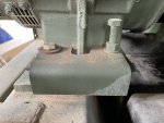
c1. Remove bolts 1 - 6 on forklift cover.
d. Remove two bolts (9), lock washers (10), washers (11), and right rear engine support (12). Discard
lock washers (10).
I heated and cooled and sprayed with penetrating oil. I did it again and let it sit overnight. This afternoon, I put the LAP over the breaker bar and there... it moved. Just a little, but it moved. I did it again, and again and again. Maybe a quarter turn at a time. It was moving! After about 50 times it occurred to me that maybe there's a nut under there somewhere. I looked under and up. Nope. I tried some more. That's when I noticed three nasty bolts in the skid rail. Now... where in the directions did it say... remove these bolts? You know bolts 1, 2 and 3 and their cousins on the other side 4, 5 and 6? Potty mouth... so I've come to the conclusion that not only do men have trouble asking for directions apparently @Guyfang has trouble giving directions. And really, why does this generator set need forklift shields? Can't y'all run your fork into the hole and straight through? And what do y'all do with said bolts 1 - 6? Is it enough that you torque them to high heaven? Noooo, you gotta put six coats of paint on them. Sheesh! Metric wrenches came in handy on these American standard bolts.

I was just so mad at myself for not picking up on that detail in the TM. Once I got the the forklift shield off, there they were: two shiny nuts. There was good news too. There was a clear shot to them where I could use my impact wrench. Had I finally caught a break? Nope. They wouldn't budge, At this point I began to worry that if I ever got them off I would never be able to torque the replacements because my torque wrench doesn't have a sumo wrestler setting. Grrr....

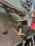
This is where I sinned. I'm sorry @Guyfang, I know you told me never to use this tool. But I broke down just this once.

IMG_1529.jpeg

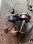
Yes, yes, I admit it. I used a vise grip to keep the nut from spinning. Eeek...

IMG_1530.jpeg


I'm so durned proud of myself! 8)
 
Top
AdBlock Detected

We get it, advertisements are annoying!

Sure, ad-blocking software does a great job at blocking ads, but it also blocks useful features of our website like our supporting vendors. Their ads help keep Steel Soldiers going. Please consider disabling your ad blockers for the site. Thanks!

I've Disabled AdBlock
No Thanks