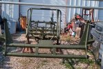
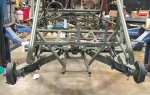
Getting the front end ready for blasting.
A quick lesson in bug front ends, the pre 1966 VW used a link pin front suspension, 66 and later used a ball joint front end, evidently the link pin was stronger as just about all the off road suspensions are link pin, the original front end used a set of leaves in a torsion configuration, there was two sets of leaves one set in each of the two "beams", they connected in the center using a square fitting that the leaves passed through and a grub screw to secure.
View attachment 882033
So when they decided they needed a wider front end they installed two sets of square fittings and grub screws and used two complete sets of springs, simply cutting off somewhat less than half of the original springs, the Chenowth built front end on the FAV is 9" over, which is a little unusual, the normal oversize is 6 and 8"
But regardless a set of oversize leaves will work in any oversize front end. (already cut)
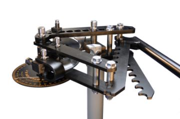
Simple enough to figure out the oversize, just measure center to center on the grub screws.
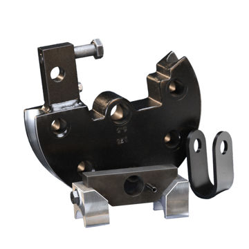
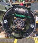
To enhance the front end adjusters are added, about 1 inch of adjustment here makes about 8" difference in height.
The special grub bolts and adjuster bolts have been replaced with standard bolts to make clean up after blasting and painting easier and to protect the threaded parts.
View attachment 882045
I wish I had taken a before picture, this adjuster was BADLY mangled, I had to straighten it out and then carefully cut the old nut out with a torch, then weld a new nut in place, not perfect but will do.
View attachment 882047
Several of the leaves were broken off, this was about half of them, the rest got blasted out,,this front end really needed some serious TLC.
View attachment 882048
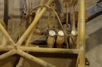
Originally it has 8 bushing, two per side per beam, they were made of what looks like a brown phenolic material, as you can see a couple of them were pretty chewed up, in fact one of the outside bushings was pushed into the beam making it useless.
View attachment 882069
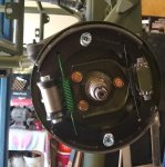
The replacement bushings are one piece, inside bushing, outside bushing and seal all in one!
View attachment 882050
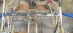
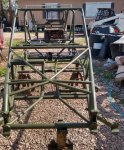
This front end was Packed from one side to the other in 30+ years of grease, what a mess!!!!
Nice to be able to see all the way through the beams!
View attachment 882055
Of course I have to dissemble and clean all of this again after blasting/painting
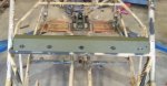
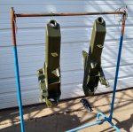
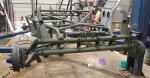
I also protected the two areas on the chassis where the numbers are stamped, the factory chassis plate and the area where the military stamped the serial number, both a very lightly stamped and are hard to read with any paint on them so I want to make sure nothing happens there, I used some .040" high density poly wrapped with a tin can..
View attachment 882057
View attachment 882067
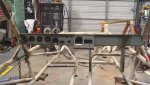
I also put bolts into any threaded holes on the chassis and any parts going to be blasted.
So we are loaded and waiting to get a coordinated time to drop it off to be blasted and primed with an epoxy primer, I will be doing the painting!


 www.jd2.com