I was thinking that it might be good to have the engine fan run continuously when I had the AC on. After having installed this way for a few months, I found it unnecessary and disconnected the AC lead shown in that diagram. It just eats HP up when you do not necessary need to extra air flow. So, yeah, not really necessary at all!
Do'oh on my part!
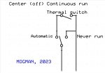
At the time I thought it was easier for me to hook it to the thermoswitch. But I guess you could hook it up on the Cadillac Valve side of course.
There is +24V directly from one of the leads on the thermoswitch. The lead on the thermoswitch with +24v is the one you cut. The other lead you does not have +24V and that is the lead you do not touch in that diagram.
Instead of using a +12V ignition source, that I had readily accessible, just use a 24V DPST relay instead and use some +24V ignition source, like tap into the run position of the ignition switch instead. That would be easier. You want an ignition switched source so if you leave the switch in the wrong position when you shutdown the engine, it will not drain your battery. Do not hook it directly to the battery. And of course, add a fuse too to where you tap it from your ignition source.
You cannot use the +24V on the Thermoswitch as the +24V IGN source as at times that lead does not get power at all so when that happens this setup will not work properly. I think it cuts power if you floor the accelerator - Fording Mode? I have definitely seen no power to that circuit.
And just forget about that AC connection if you don't have AC - actually forget about it either way!
View attachment 932327
Hope this helps.


")


