• Steel Soldiers now has a few new forums, read more about it at: New Munitions Forums!

  • Microsoft MSN, Live, Hotmail, Outlook email users may not be receiving emails. We are working to resolve this issue. Please add support@steelsoldiers.com to your trusted contacts.

M998 no alternator charging and no glow plug light

kevnam

New member
9
7
3
Location
Iowa
Hello. I have an m998, two thing happened at once. I started it the other day and noticed the glow plug light did not come on. Then as I was driving I noticed the voltmeter was in the yellow, not charging. I cleaned grounds on the shunt and terminals on alternator, still not working. Testing many times past couple of days, glow plugs worked once and charged for a few seconds... Then back to yellow,and no plugs again.
I do NOT have 24v at the IGN terminal on the regulator with the ignition switch on. If I jump power from 24+ on alternator to the IGN on regulator, then the alternator works perfectly and charges at 28.6v high idle.but no glow plugs yet, and voltmeter does not cycle down to yellow off and on a few times , like when it's a cold start up.
Question.... Does power leave the ignition switch and goes directly to IGN terminal on regulator , or does it go thru the control box first? I cleaned many terminals and no help. None were even corroded either. This Humvee is very clean. Being I got it to work a couple of times, I have to believe it's a bad wire or connection somewhere. It's odd both things happened on one start up the other day.
100 amp niehoff dual voltage alternator 12447110, n3135 regulator
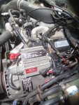
6.5 engine , m998

Thanks for any/ all help.
 

Mogman

Moderator
Staff member
Moderator
Steel Soldiers Supporter
6,314
8,864
113
Location
Papalote, TX
There is a relay (contactor) in the EESS/PCB box that is likely bad, try tapping on it lightly with a hammer with the run switch on, sometimes that will get the relay to kick in,,if that is the problem the heater fan should also not be working as it is also powered by that relay.
The relay is fairly easy to replace.
 
Last edited:

kevnam

New member
9
7
3
Location
Iowa
There is a relay (contactor) in the EESS/PCB box that is likely bad, try tapping on it lightly with a hammer with the run switch on, sometimes that will get the relay to kick in,,if that is the problem the heater fan should also not be working as it is also powered by that relay.
The relay is fairly easy to replace.
Thanks mogman. You are correct, the fan does not work either. It did come o. For 2 seconds while I was hitting the dash with my hand.... Then quit again. So,,, I did the whole ground upgrade this afternoon. The only one I found to be corroded was the one on the firewall. I added 4 new grounds as suggested in the forum.
I then connected the batteries and nothing changed, no heater , glow plugs , and no 28 charging voltage...batteries are newer intestate correct batteries. And are very strong at 24. 8volts standing. I was hoping to find the relay in the control box as you stated, however my is all electronic inside, no relays or solenoids. Apparently I have the undesirable early box???
P.s..... when I jump from alternator + to IGN on regulator, then it charges perfect at 28.4 and the heater fan works, just no glow plugs on start up. Is it ok to leave this jumper there all the time? And do I just have a bad wire... Because I have no voltage at IGN terminal when the key is turned on , unless i run the jumper of course. Thanks again all.
 

Attachments

kevnam

New member
9
7
3
Location
Iowa
There is a relay (contactor) in the EESS/PCB box that is likely bad, try tapping on it lightly with a hammer with the run switch on, sometimes that will get the relay to kick in,,if that is the problem the heater fan should also not be working as it is also powered by that relay.
The relay is fairly easy to replace.
Also, there are 2 wires on my IGN terminal on the regulator; a small one and a large 6 or 8 gauge wire. This large wire looks like it goes to a pin in the EES connector over by the washer fluid reservoir. What I don't understand is, there is no large wire that size leaving the control box on the other connection under the dash. ,should this large wire,to directly to batteries instead? Wouldn't this charge current going thru this box fry it?
 

Mogman

Moderator
Staff member
Moderator
Steel Soldiers Supporter
6,314
8,864
113
Location
Papalote, TX
Well no you cannot leave the jumper in as it will drain the batteries and possibly damage the regulator.
The 6ga wire should be marked 5A and that should go to the regulator ign/sense. terminal, there is a #568 that should be abandoned and a #2 that goes to the AC terminal.
Huh, no relays in the SSI box,,,
I think that SSI is an old box, time to upgrade to smart start or one of the manual boxes, all others are on borrowed time to begin with.
 

Mogman

Moderator
Staff member
Moderator
Steel Soldiers Supporter
6,314
8,864
113
Location
Papalote, TX
Also, there are 2 wires on my IGN terminal on the regulator; a small one and a large 6 or 8 gauge wire. This large wire looks like it goes to a pin in the EES connector over by the washer fluid reservoir. What I don't understand is, there is no large wire that size leaving the control box on the other connection under the dash. ,should this large wire,to directly to batteries instead? Wouldn't this charge current going thru this box fry it?
There is a large wire running from the PCB to the batteries, it connects inside the PCB to the alt (5A) when in the run position,,,ORIGINALLY it was connected to the output of the 60A alternator trough the PCB to the batteries, and the #568 wire exited the 60A alt ign/sense. Actually the #5A and the #568 are coinnected at the same point in the PCB
SOO when upgraded to a 100/200/400A alt the upgraded alt requires more current to excite (ign/sense) the alt so the small #568 is abandoned the the original charge wire 5A is used to excite the 100/200/400A alt and a separate wire (or two in the case of the 400A) large enough to handle the increased charge current is run directly to the battery (the one with the spiral loom in your picture)
I assume they just connected 5A and 568 together instead of abandoning 568 which is fine.
I hope this helps..
 
Last edited:

Mogman

Moderator
Staff member
Moderator
Steel Soldiers Supporter
6,314
8,864
113
Location
Papalote, TX
The original idea was the PCB Protection Control Box
It disconnected everything that may get damaged if the batteries were to be connected backwards, that is why the 60A alt output was run through the PCB as everyone knows if you hook up the batteries backwards the alt will fry.
SO the PCB would not connect to anything that could be damaged unless it detected the batteries were connected correctly.

All that went out the window when they started upgrading to the 100/200/400A alternators, now the alt output is connected directly to the batteries so if the batteries are connected backwards sparks will fly and stuff gets fried.

But because of parts logistics they never really redesigned the PCB so they would be compatible with both types of systems, even though it is a piss poor and poorly implemented design to begin with.
 

kevnam

New member
9
7
3
Location
Iowa
Yeah mogman, I think my box part number is the oldest version. I can't open the box very far, as the "ribbon" connection that goes to the round pin harness (under the dash), is only a little over an inch inside the box ... And it's soldered to the pins and to the pcb board. Can only open the box a couple inches. I see nothing burnt on the board, but it is all very small chips, capacitors, etc... No relays like I was hoping to see.
Can I upgrade to any new style box? I see there are many different numbers. And also, I guess a used box like mine isn't worth the time or money, as they are prone to failures ???
One more question, what is the manual box you speak of?
 

Mogman

Moderator
Staff member
Moderator
Steel Soldiers Supporter
6,314
8,864
113
Location
Papalote, TX
Yeah mogman, I think my box part number is the oldest version. I can't open the box very far, as the "ribbon" connection that goes to the round pin harness (under the dash), is only a little over an inch inside the box ... And it's soldered to the pins and to the pcb board. Can only open the box a couple inches. I see nothing burnt on the board, but it is all very small chips, capacitors, etc... No relays like I was hoping to see.
Can I upgrade to any new style box? I see there are many different numbers. And also, I guess a used box like mine isn't worth the time or money, as they are prone to failures ???
One more question, what is the manual box you speak of?
Yes you can upgrade, look at this sticky for what temp sensor you need for any particular box.
There is a member here [B]Milcommoguy[/B] that builds manual boxes, or you can build one yourself if so inclined.
 

kevnam

New member
9
7
3
Location
Iowa
Yes you can upgrade, look at this sticky for what temp sensor you need for any particular box.
There is a member here [B]Milcommoguy[/B] that builds manual boxes, or you can build one yourself if so inclined.
Well mogman, that is strange. Inside my box looks nothing like any of these! Even the one with the same part number as mine has a huge solenoid in it. Mine has nothing larger than a pencil eraser in it. It has twice the electronics as any of them pictured. I will have to get a pic tomorrow. I just can't open it far because of,the short ribbon. And..... I can't remove the board from the case because the other pin connector is soldered directly to the board, through the casing. It can't be removed without simultaneously desoldering all pins at once.
I would love to gut it and build my own. I am skilled din electronics and wiring. Time is the main factor. It would be great if I knew what relays to use and wiring for all the other functions as well.
 

Mogman

Moderator
Staff member
Moderator
Steel Soldiers Supporter
6,314
8,864
113
Location
Papalote, TX
You might look at this,
 

kevnam

New member
9
7
3
Location
Iowa
You might look at this,
Thanks for all your help on my start box, I'm going to call camo and go manual I believe. .... But I saw you have listed that your m998 has a 6l80e in it. I love the gear spread of the 6l80e. But do they make that in a non-electronic version. Or is it simpler to put in a standalone tcm for the tranny. Also how is the fitment, any drive shaft mods? I have my own shop with a hoist. I was thinking of a built 700r4 because of the smaller size. Also what did you use for your gear selector with the six speed? No hurry, this will be a winter project once I get the glow plugs working.
 

Mogman

Moderator
Staff member
Moderator
Steel Soldiers Supporter
6,314
8,864
113
Location
Papalote, TX
Thanks for all your help on my start box, I'm going to call camo and go manual I believe. .... But I saw you have listed that your m998 has a 6l80e in it. I love the gear spread of the 6l80e. But do they make that in a non-electronic version. Or is it simpler to put in a standalone tcm for the tranny. Also how is the fitment, any drive shaft mods? I have my own shop with a hoist. I was thinking of a built 700r4 because of the smaller size. Also what did you use for your gear selector with the six speed? No hurry, this will be a winter project once I get the glow plugs working.
It has a stand alone controller, there was allot of custom work required including a custom made clocking ring for the transfer case, I used a 4 speed shifter
 

kevnam

New member
9
7
3
Location
Iowa
Sounds like a lot more work than what I am willing to put into the humvee. I will probably use a built 700r4 when time permits.
One more question on the start box that I don't understand... Why do I not get 24v at the IGN terminal when I turn the switch to run? From everything I see on the forums and diagrams, the voltage goes from the switch out to the IGN on regulator. I never get that voltage, so I. Still thinking I may have a bad switch or wire. Id hate to replace the expensive control box unnecessarily. Thoughts?
 

Mogman

Moderator
Staff member
Moderator
Steel Soldiers Supporter
6,314
8,864
113
Location
Papalote, TX
The only thing the run switch powers directly is the inst. panel, the run solenoid in the IP and the start solenoid, all other loads are provided from the PCB/EESS box, the run switch could not handle the current required for the alt, heater blower etc.
I am not sure what schematic you are looking at but the PCB/EESS box in the schematics are just a logical representation of what is going on not the actual internal workings, that should be stated on the schematics
 
Last edited:

kevnam

New member
9
7
3
Location
Iowa
The only thing the run switch powers directly is the inst. panel, the run solenoid in the IP and the start solenoid, all other loads are provided from the PCB/EESS box, the run switch could not handle the current required for the alt, heater blower etc.
I am not sure what schematic you are looking at but the PCB/EESS box in the schematics are just a logical representation of what is going on not the actual internal workings, that should be stated on the schematics
Soo... The 24v that should be present at the IGN terminal on the regulator (when the switch is in run position), comes from the eess box. And this is a voltage to "excite" the alternator to charge 28 volts out of the big main lug on the alternator, correct? .... The IGN terminal is an "input" terminal, not output. If so, that makes so much more sense, and my box is definitely bad.
And when I jump 24v to the IGN terminal, it's back feeding to the box and the fan circuit, which is why my fan works only when I jump power to the IGN terminal.
 

Mogman

Moderator
Staff member
Moderator
Steel Soldiers Supporter
6,314
8,864
113
Location
Papalote, TX
Soo... The 24v that should be present at the IGN terminal on the regulator (when the switch is in run position), comes from the eess box. And this is a voltage to "excite" the alternator to charge 28 volts out of the big main lug on the alternator, correct? .... The IGN terminal is an "input" terminal, not output. If so, that makes so much more sense, and my box is definitely bad.
And when I jump 24v to the IGN terminal, it's back feeding to the box and the fan circuit, which is why my fan works only when I jump power to the IGN terminal.
You got it!
 
Top
AdBlock Detected

We get it, advertisements are annoying!

Sure, ad-blocking software does a great job at blocking ads, but it also blocks useful features of our website like our supporting vendors. Their ads help keep Steel Soldiers going. Please consider disabling your ad blockers for the site. Thanks!

I've Disabled AdBlock
No Thanks