• Steel Soldiers now has a few new forums, read more about it at: New Munitions Forums!

  • Microsoft MSN, Live, Hotmail, Outlook email users may not be receiving emails. We are working to resolve this issue. Please add support@steelsoldiers.com to your trusted contacts.

CTIS

You were able to work the solenoids using the jumpers right, so they are probably OK. The best test for the wet tank switch is at the CTIS controller connector. When the tank goes over 117 PSI you snould see it close and complete a low resistance circuit between pin T in the connector and ground.

I would work that governor set point down towards 125 PSI.

it could be that you have a bad pressure sensor on the PCU. While you have the PCU apart, unscrew the sensor and inspect it for any debris in its sensor port. You could also check resistance between the pins in the CTIS controler connector and the pressure sensor connector at the PCU install location. Pins j, b and c (lower case) should connect to pins A, B and C respectively in the pressure sensor transducer connector at the PCU.

You could also probe the wires thru the insulation with a pin to the pressure sensor with controller and sensor connected and powered. it is a 0-5v 0-100 PSI sensor. The controller sends 5v and ground to two of the pins on the sensor and the sensor returns a 0-5v signal based on the pressure it senses. 5v divided by 100 = .05v per pound of pressure, so 14PSI of atmospheric air pressure should yield ~.73V on the sense wire…

contact Superman here on steel soldiers, he had PCU rebuild parts. Great guy to work with!
Roger on reducing to 125.

I did take take that sensor off the PCU…and it was locked on there right. The only thing in it was a little moisture. I short it with some spray and reinstalled.

At next opportunity I’ll check continuity. If that all checks out, do you suggest a new sensor? If so, do you happen to have a part number?

After looking at your manual setup, I’m inclined to go that route due to it simplifying the system.

Thanks again for your help!

John
 
Hate to say it but instead of guessing you *could* build the interface cable, download the free software from Dana and know what the problem is *for sure*.

Do the A0 trucks have ABS? I have the Wabco software too - identified a dirty wheel speed sensor on a truck with it yesterday. Huge time savings when it can tell you which wheel isn't reporting wheel speed instantly!
I am absolutely not opposed to this at all. Do you happen to have a link or picture of the how-to?

Thanks.

John
 

GeneralDisorder

Well-known member
Steel Soldiers Supporter
2,034
5,224
113
Location
Portland, OR
I am absolutely not opposed to this at all. Do you happen to have a link or picture of the how-to?

Thanks.

John
No - but all you need is 4 wires and some connectors in principle. This page has the J1708 pinout:


Then you need an RP1210 compliant adapter such as the Dearborn Protocol Adapter III or IV. Laptop and software.
 

Ronmar

Well-known member
3,846
7,476
113
Location
Port angeles wa
Roger on reducing to 125.

I did take take that sensor off the PCU…and it was locked on there right. The only thing in it was a little moisture. I short it with some spray and reinstalled.

At next opportunity I’ll check continuity. If that all checks out, do you suggest a new sensor? If so, do you happen to have a part number?

After looking at your manual setup, I’m inclined to go that route due to it simplifying the system.

Thanks again for your help!

John
If the wet tank pressure sw is operating properly, closed above ~117, open below ~89, I would not call the pressure sensor bad untill I confirmed its input and output.

The pressure sensor gets ground and 5V input from the controller on 2 of its wires(pins C and B respectively). and outputs a 0-5V signal based on the pressure it sees on the third wire(Pin A). If you connect the black lead of a voltmeter to ground, and use a needle to push thru the insulation on the 3 wires connecting to the PCU pressure sensor, with the wet tank above 117 and the truck ign sw turned on, you should see 0v on the wire connected to pin C, and 5V on the wire connected to B at the PCU wire harness. I would probe B and C with the meter to insure it has a good circuit from the controller(Black lead to pin C and red lead to pin B) Probing the wire for pin A measured to ground should yield a 0-5v signal that represents the pressure that the sensor sees.

if the controller is not delivering the 0 and 5 v inputs the controller could be the issue, or the wiring between controller or sensor is not allowing the connection… Garbage in = Garbage out…

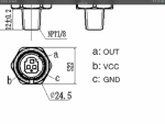
you could actually remove the sensor and connect it to a regulated air source and check the output across its entire 0-100PSI/0-5v span by varying the pressure applied, While it has the ground and 5v input on pins C and B… this is a fairly standard sensor type. Here is a pinout diagram.

IMG_3738.png
 
If the wet tank pressure sw is operating properly, closed above ~117, open below ~89, I would not call the pressure sensor bad untill I confirmed its input and output.

The pressure sensor gets ground and 5V input from the controller on 2 of its wires(pins C and B respectively). and outputs a 0-5V signal based on the pressure it sees on the third wire(Pin A). If you connect the black lead of a voltmeter to ground, and use a needle to push thru the insulation on the 3 wires connecting to the PCU pressure sensor, with the wet tank above 117 and the truck ign sw turned on, you should see 0v on the wire connected to pin C, and 5V on the wire connected to B at the PCU wire harness. I would probe B and C with the meter to insure it has a good circuit from the controller(Black lead to pin C and red lead to pin B) Probing the wire for pin A measured to ground should yield a 0-5v signal that represents the pressure that the sensor sees.

if the controller is not delivering the 0 and 5 v inputs the controller could be the issue, or the wiring between controller or sensor is not allowing the connection… Garbage in = Garbage out…

you could actually remove the sensor and connect it to a regulated air source and check the output across its entire 0-100PSI/0-5v span by varying the pressure applied, While it has the ground and 5v input on pins C and B… this is a fairly standard sensor type. Here is a pinout diagram.

View attachment 905597
@Ronmar. I verified I have continuity between pins a, b and J on the ECU and the PCU pressure transducer harness pins a, b and c.

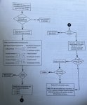
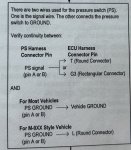
Also, using the Spicer service manual, I verified that the wet tank pressure switch is opening and closing on or about the prescribed pressures. See the attached picture for what I followed.

Last, using page 30 of the Spicer manual, I also confirmed that the voltage on pin b on the PCU transducer harness outputs 5.03v.

According to this troubleshooting step, I need a new PCU sensor. Do you think this is time for a new pressure transducer for the PCU? Should I buy one that is rated at 100 psi? This one?


Thanks.

John

AE23EE28-E04A-4447-847B-EC33C45E7367.jpeg871912AE-1956-47A5-BB09-E14C976B50E2.jpeg
 
Last edited:

Ronmar

Well-known member
3,846
7,476
113
Location
Port angeles wa
I always found that style of troubleshooting a little arrogant. Oh there can be nothing wrong with our controller.., if the wiring is good and 5v source power is making it to the pressure sensor and it doesnt work it must be a bad sensor, instead of actually probing the line to see what the sensor output really is…:)

yes, the PCU pressure sensor is probably bad. If that one has the correct connector style, it is a pretty standard configuration.
some have also swapped in a 0-150 psi sensor. if your highway pressure is 55PSI, putting in a 0-150 psi sensor will cause it to run at about 75PSI which is a better highway pressure for these tires… if your control unit is already programmed for a higher highway pressure, then you would want the 0-100 psi sensor.
 
Last edited:
I always found that style of troubleshooting a little arrogant. Oh there can be nothing wrong with our controller.., if the wiring is good and 5v source power is making it to the pressure sensor and it doesnt work it must be a bad sensor, instead of actually probing the line to see what the sensor output really is…:)

yes, the PCU pressure sensor is probably bad. If that one has the correct connector style, it is a pretty standard configuration.
some have also swapped in a 0-150 psi sensor. if your highway pressure is 55PSI, putting in a 0-150 psi sensor will cause it to run at about 75PSI which is a better highway pressure for these tires… if your control unit is already programmed for a higher highway pressure, then you would want the 0-100 psi sensor.
Their guide does that the tone the way you describe.

I ordered the 0-100 as mine is a tractor (M1088) and the stock setup “should” be programmed for 80ish PSI. If it’s wrong, I’ll replace it.

I’ll post an update when this gets here on Saturday.

Thanks.

John
 
Top
AdBlock Detected

We get it, advertisements are annoying!

Sure, ad-blocking software does a great job at blocking ads, but it also blocks useful features of our website like our supporting vendors. Their ads help keep Steel Soldiers going. Please consider disabling your ad blockers for the site. Thanks!

I've Disabled AdBlock
No Thanks