• Steel Soldiers now has a few new forums, read more about it at: New Munitions Forums!

  • Microsoft MSN, Live, Hotmail, Outlook email users may not be receiving emails. We are working to resolve this issue. Please add support@steelsoldiers.com to your trusted contacts.

[Q] 60 AMP to 200 AMP Gen upgrade on M998

FlameRed

Well-known member
Steel Soldiers Supporter
345
527
93
Location
Florida
Hello,

Once again I ask the collective for guidance on a question I came up with regarding upgrading a 60 AMP to 200 AMP gen.

Please reference this YouTube:

at the 16:30 mark. The creator references that there is a second cable supplied in the conversion kit that goes to the first battery 12V terminal supplied in his upgrade kit. I was only supplied a single new 24V battery cable that goes to the 24V terminal, and not a second cable for this 12V connection. I am not sure why there seems to be a difference. The instructions I have do not reference this 12V second cable. The Kit I received is HMMWV M998 M1026, 200 AMP GENERATOR ALTERNATOR Upgrade KIT PN 57K3520.

My first question is, do I need to run my own supplied 12V cable from the regulator to the 12 battery connections? Or is this second cable not necessary? Or should I run one?

Second question. The author also states at 17:15 mark, that his instructions state to run a supplied jumper from the 14V regulator terminal to ground on the 4 speed transmission (which I have). But he states that is not necessary based on a thread here? My instructions state to run this jumper also, but does not mention the transmission type.

Any help would be most welcome, as I do not wish to experiment and perhaps burn out a brand new regulator!

Thanks in advance!
 

Mogman

Moderator
Staff member
Moderator
Steel Soldiers Supporter
6,930
9,587
113
Location
Papalote, TX
Many upgrades done to Basic and A1 trucks did not include the 14V wire because without the 4 speed they saw no need to balance the batteries, if you are going to pull any power from the 12V connection between the batteries you need to install this wire.
I have seen the 14V tap on the regulator not connected at all and grounded when not used, there is no voltage on that tap when charging unless it is connected to the 12V connection on the batteries. (it is evidently "smart")
I suspect the dual voltage system actually needs a load on the 12V connection to work properly when the 14V tap is connected.
I ran a temp wire on the R1 I am dismantling and saw the voltage a little high on the rear battery with no load.

EDIT, so it does not surprise me your upgrade kit did not include the 14V wire, I could not remember so I went and looked, the kit I bought for the Detroit did not have the 14V wire as it has my own asphalt loom on it.
 
Last edited:

Retiredwarhorses

Well-known member
Steel Soldiers Supporter
4,397
4,181
113
Location
Brentwood, Calif
The 200amp kits were for v-belt trucks, not for A2 and above trucks, therefore they would not need to provide the
additional cable because the truck is running a 3 speed transmission
 

FlameRed

Well-known member
Steel Soldiers Supporter
345
527
93
Location
Florida
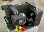
Just wanted to double check the wiring for the three connectors on the 200 AMP regulator. I ran a 12V heavy gauge battery cable to the first battery positive terminal and will connect that to the big 12V lug.

There are three terminals on the regulator.
  • On one side of the regulator - there are two terminals, there is a red one and a beige insulator on the terminals, and a yellow dot painted between those two terminals.
  • On the other side - there is one terminal, another beige one - no paint marks.

According to the instructions,
  • the red terminal gets lead 5A, shown with the red arrow in the picture below.
  • The yellow terminal gets lead 2A. There is a yellow dot painted where the yellow arrow is shown.
I checked with Niehoff as they don't seem to have diagrams published for this puppy. Does this seem correct?

s-l960.jpg
 

86humv

Well-known member
Steel Soldiers Supporter
1,700
501
113
Location
Texas
Wh
Just wanted to double check the wiring for the three connectors on the 200 AMP regulator. I ran a 12V heavy gauge battery cable to the first battery positive terminal and will connect that to the big 12V lug.

There are three terminals on the regulator.
  • On one side of the regulator - there are two terminals, there is a red one and a beige insulator on the terminals, and a yellow dot painted between those two terminals.
  • On the other side - there is one terminal, another beige one - no paint marks.

According to the instructions,
  • the red terminal gets lead 5A, shown with the red arrow in the picture below.
  • The yellow terminal gets lead 2A. There is a yellow dot painted where the yellow arrow is shown.
I checked with Niehoff as they don't seem to have diagrams published for this puppy. Does this seem correct?

View attachment 908922
What is that thing....its not a Hmmwv part.
 

FlameRed

Well-known member
Steel Soldiers Supporter
345
527
93
Location
Florida
The terminals are not labeled?
The +24V, +12V are labeled. The red terminal is easily identifiable, and gets connected to 5A. The other two smaller terminals are not labeled, and are both beige. There is a yellow dot painted between the red and beige terminals on one side, which leads me to believe that beige one gets 2A.

But no, neither of these two beige terminals are labeled in any way.
 

Mogman

Moderator
Staff member
Moderator
Steel Soldiers Supporter
6,930
9,587
113
Location
Papalote, TX
I will be interested in what Niehoff says, that alt has one more terminal than the "regular" 200A
I have seen those for sale and wondered if they would fit, you answered that.
One of those terminals should have an AC voltage on it when charging, that would go to wire 2A, it tells the PCB/EESS that the engine is running and on some installations gives the tach the rpm signal.
 

FlameRed

Well-known member
Steel Soldiers Supporter
345
527
93
Location
Florida
I'll post my final results, which I consider excellent for me being a old feeble newbee.

This generator seems to function just fine as wired according to the diagrams shown above. The stock guage on the dash now shows a reading in the middle of the green range whereas before with the 60 amp generator that gauge read just minimum in the green range. It does seem to fluctuate a little, where as the 60 amp was steady.

After sitting for a couple months, I did notice a couple strange anomalies, which I think are unrelated. First, when I went to start it, I did not see a red wait light after turning the igintion on. This has happened to me before and it was a bad ground on that wait light. Most of the time it just starts working later. It started fine, so I think it is still the same thing.

The digital voltage gauge I had installed was reading 10 volts which is new, where it used to read 27 volts with the 60 amp but that gauge I installed so it is likely something ground related again. I checked the batteries and the outputs of the 200 Amp and they were as expected, I think this is unrelated most likely. I'll have to investigate.

I paid my dues with the usual rusted, stuck bolts, and threaded holes that were crossed and a PITA to remove. Retapped them with new bolts once I got the old ones out. Fortunately I did not have any that broke off in the head.

I know I had a 50 year old made in the US V-belt tensioner tool that I have not used in decades but I could not find it :mad: I bought a crapulant chinese V-belt tensioner tool that I got off of flea-bay and it snapped off the end before I even started tightening it. :poop: The one thing I did not expect is that the triple belts for the 200 AMP need to be much tighter. I used all my (meager) strength with a breaker bar but that was not evidently good enough. I'll have to try again.

EDIT: Found the issue with the digital volt gauge was I had forgot to connect one of the ground leads I had disconnected.

And it seems that the wait light was burned out. Voltage is present when appropriate. Replaced.

All good now.
 
Last edited:
  • Like
Reactions: OBX

Mogman

Moderator
Staff member
Moderator
Steel Soldiers Supporter
6,930
9,587
113
Location
Papalote, TX
I'll post my final results, which I consider excellent for me being a old feeble newbee.

This generator seems to function just fine as wired according to the diagrams shown above. The stock guage on the dash now shows a reading in the middle of the green range whereas before with the 60 amp generator that gauge read just minimum in the green range. It does seem to fluctuate a little, where as the 60 amp was steady.

After sitting for a couple months, I did notice a couple strange anomalies, which I think are unrelated. First, when I went to start it, I did not see a red wait light after turning the igintion on. This has happened to me before and it was a bad ground on that wait light. Most of the time it just starts working later. It started fine, so I think it is still the same thing.

The digital voltage gauge I had installed was reading 10 volts which is new, where it used to read 27 volts with the 60 amp but that gauge I installed so it is likely something ground related again. I checked the batteries and the outputs of the 200 Amp and they were as expected, I think this is unrelated most likely. I'll have to investigate.

I paid my dues with the usual rusted, stuck bolts, and threaded holes that were crossed and a PITA to remove. Retapped them with new bolts once I got the old ones out. Fortunately I did not have any that broke off in the head.

I know I had a 50 year old made in the US V-belt tensioner tool that I have not used in decades but I could not find it :mad: I bought a crapulant chinese V-belt tensioner tool that I got off of flea-bay and it snapped off the end before I even started tightening it. :poop: The one thing I did not expect is that the triple belts for the 200 AMP need to be much tighter. I used all my (meager) strength with a breaker bar but that was not evidently good enough. I'll have to try again.
IMHO anyone with a HMMWV should buy the HMMWV tool kit 57K0267, it includes a belt tension gauge along with many of the tools necessary to correctly maintain the vehicle, in the overall view of the HMMWV world they are affordable.

https://www.ebay.com/itm/3257303219...PhtOPgz8Tz0mIEspMhXtBDqQ==|tkp:Bk9SR5bzitjyYg
 

Mogman

Moderator
Staff member
Moderator
Steel Soldiers Supporter
6,930
9,587
113
Location
Papalote, TX
Or the kit 57K0268, this kit has all the tools from the 0267 kit plus much more, actually I wish I had purchased this kit, even though I already had the engine sling which is a God send for removing engines.

Engine Lifting Sling DRF 561
Belt Tension Gauge
Runflat Compressor DRF 2688
Drive Transmission Handle DRF 551
Seal-Installer DRF 21359
Rack Piston Steer Gear Hand Tool DRF 21552
Output Shaft Inserter DRF 22661
Diesel Timing Gage DRF 35169
Bearing & Bushing Inserter DRF 576
Bearing/Bushing Remover DRF 6221
Bearing/Bushing Inserter & Remover DRF 6278
Extended Straight Cherry Max FSI F1074H
Right Angle Cherry Max Pulling Head FSI F1075H
Offset Cherry Max Pulling Head FSI F1076H
Cylinder Compression Tester Adapter SPX J-26999-30
1/4 Drive Socket Wrench SPX J-35165
Pipe to Tube Elbow SPX J-35208
Quick Coupling Half SPX J-35209
Hydraulic Valve Lifter Remover SPX J29834
Fuel Injection Nozzle Remover SPX J29873
Preload Bearing Steering Wrench SPX J7624
16MM 3/8 Drive Open End Crowfoot STP 4916MCF
19MM 3/8 Drive Open End Crowfoot STP 4919MCF
3/8 Drive 5/32 Hex Bit STP 49905/32
Tach & Time Tester
Engine Timing Tool Kit DRF 530
Cylinder Compression Tester SPX J-6692B
Tension Meter DRF 371
Power Steering Analyzer DRF 12342943
Yoke Seal Installer DRF 29162
Tire Rod Seperator ALN 2288
Pump Pulley Installer DRF 553
Geared Hub Input Inserter DRF 579
Geared Hup Inserter DRF 580
Geared Hub Socket Wrench DRF 581
Blind Rive Tool Kit FSI D100-MIL-1
Drive Inspection Mirror SET 317
Misc Torque Wrenches, Open End Crowfoots, Hex Bits & Adapters

 
  • Like
Reactions: OBX

Milcommoguy

Well-known member
Supporting Vendor
1,710
2,265
113
Location
Rosamond, CA
Old feeble newbee from a desert rat here, LOL. Throwing this out there... The 60 Amp alternator have an voltage adjustment. Easy to get at and set. 200 amp units do not.

WAIT LED is supplied wth 24 volts and is controlled by the not so "smart control box". It provides a logic ground (pulls low) from the computer to activate.
Not sure of your description cleaned ground of WAIT LED, BUT nasty old grounds are talked about here and may become an issue through out the truck over time. Old truck, old man. 👴 Remove clean and re-tighten.

If one can trust the digital voltmeter ?? 10 volts clearly not right. Could be a ground ? ... as every other problem here points to a ground, But not necessarily.

Broken bolts and busted knuckles you could have a broken box, CAMO
 
Last edited:

TOBASH

Father, Surgeon, Cantankerous Grouch
Steel Soldiers Supporter
Supporting Vendor
3,578
3,488
113
Location
Brooklyn, NY
Camo was and is radio/electronic former military guy. Don’t trust the built in meters and always defer to separate voltmeter and ammeter.

Might wanna listen to him.

Just sayin’.

Also, I found and keep finding working bargain regulators on a certain website for less than $200.
 
Top
AdBlock Detected

We get it, advertisements are annoying!

Sure, ad-blocking software does a great job at blocking ads, but it also blocks useful features of our website like our supporting vendors. Their ads help keep Steel Soldiers going. Please consider disabling your ad blockers for the site. Thanks!

I've Disabled AdBlock
No Thanks