hawk-aggie
Active member
- 112
- 66
- 28
- Location
- College Station, Texas
First off, I have a couple of manuals for this unit. One is the Service Manual for the engine. The other is the instruction manual for the generator. I have been unsuccessful in locating any TMs.
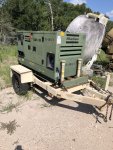
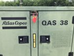
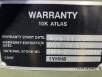
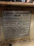
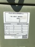
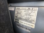
We have a surplus military Atlas Copco QAS38 YdS TNV 33.3Kw generator. It does not start with a conventional ignition switch. It has an electronic start sequence - flip the main switch, it goes through a pre-heat process, then it's supposed to crank the engine and start. Here's what I've got.
It has new oil and filters.
It has new fuel filters.
It has fuel.
The fuel system has been primed via the hand pump on the fuel injector pump.
It has 2 12v batteries connected in parallel. Voltage is 12.55vdc.
It has 2 starter relays in the circuit. Voltage at both relays is 12.55vdc.
Voltage at starter is 12.55vdc. No, I have not jumped the starter to see if the engine will turn over.
Voltage at alternator is 12vdc.
There is DC power to the starter switch, which has 7 LEDs on it. LED 1 indicates that the electrical system of the engine is energized. It works - solid green. LED 2 indicates that the glow plugs are warming up. It works - flashes green. It should go out after about 10-12 seconds, but cycle 3 times, then goes out. LED 4 indicates that there is no AC input (< 75 V line-to-neutral) is present. It works - solid red. Those are the only 3 LEDs that work currently. [L3 is the alternating charging indicator. L5, L6 and L7 are overseen shutdown, coolant temperature fault and oil pressure fault indicators respectively. Would only know if L3 and L5-7 are working when the generator gets running.]
The 12vdc panel light does not come on when the light switch is on. The light bulb looks like a large tubular glass fuse. It has continuity.
There is a push button fuse/circuit breaker on the front of the control panel. Admittedly, I have not checked it for continuity, because I just thought of it as I'm writing this inquiry.
I have checked the Dip-switches on the back of the control panel and reset them as shown in the manual.
It did not come with a magnetic pickup. I bought a new one and installed it based on my experience with the MEP-type generators we have. I have not found any guidance on exact set up yet.
Also, there is an 8 or 6 gauge yellow/green cable that runs to the AC ground bus bar behind the control panel that was disconnected when we got the unit. Typically, yellow/green is an indication of an earth ground. Normally, I would say the yellow/green cable should be connected to the frame of the generator or the trailer, but there's no indication of where it might have been attached.
I have electrical schematics, but they are hard to follow from page to page. It's likely that I missed what I'm looking for, even after reviewing them more than a dozen times. When I do find something tat I want to go check, I've no roadmap to tell me where the part I want to check is located.
Here's the punch line. I've been working on this thing off and on for nearly a year. I need a reset. Give me some tips regarding where to start diagnosing the start sequence.


