• Steel Soldiers now has a few new forums, read more about it at: New Munitions Forums!

  • Microsoft MSN, Live, Hotmail, Outlook email users may not be receiving emails. We are working to resolve this issue. Please add support@steelsoldiers.com to your trusted contacts.

Test running the 803 in the house.

jaybird67k

Member
60
20
8
Location
Texas
Got the 803 hooked up to the house for the last hour and have a few questions.
First off my percentage load meter isn't working so I'll have to figure that out.
I've trimmed my voltage and hertz.
When I check amps across L1 and L3 I get 42amp on one leg and 36-38 on the other.
Is this normal?
Any help on the percentage load meter troubleshooting would be greatly appreciated.

Thanks, Jason
 

jaybird67k

Member
60
20
8
Location
Texas
Thanks !
How should I go about troubleshooting the percentage load gauge. I've tapped on it and loosened the connections and retightened.
I had to make about 20 new connections when I got this unit because a rat had been living inside and chewing. Everything is working except the % load gauge.

Thanks, Jason
 

jaybird67k

Member
60
20
8
Location
Texas
On one side of the switch the terminals are odd numbered and the terminals on the other side are even numbered.
Yes I seen that it was. So your saying the other side goes up to #44 ?
If it does the CT coil is blocking me seeing it. I will get a mirror today.

Thanks Kloppk
 

jaybird67k

Member
60
20
8
Location
Texas
Made the broke connection going to S8 #44 and it still don't work 😭
Checked continuity between gauge going to S8 and S6 and its good.
Should I have 24v on one side of the gauge to ground?

Thanks, Jason
 

kloppk

Well-known member
Steel Soldiers Supporter
2,075
3,386
113
Location
Pepperell, Massachusetts
Should I have 24v on one side of the gauge to ground?
No.
The %Load meter M8 is not connected to +24 volts or chassis ground. The %Load meter is an AC Current meter. 0-1 Amp Full Scale

In a nutshell...
The 3 Current Transformers in CT assembly each output a current that's proportional to the load they are sensing on the 3 legs of the generator.
The current from CT2 flows thru the %Load meter with the set is set to 120/240 mode and the AM-VM is set to the 3 o'clock position.
Here is a diagram showing the circuitry assuming the set is set to 120/240 mode and the AM-VM is set to the 3 o'clock position.

At 0% load the current thru M8 would be 0.000 amps.
At 100% load the current thru M8 would be 0.752 amps.
At 133% load the current thru M8 would be 1.000 amps.

The current flowing thru the burden resistors causes a voltage to develop across them. K8 monitors those voltage to determine if there is an OL or SC condition.
At 100% load the voltage K8 receives is 5.6 volts AC.
At 133% load the voltage K8 receives in 7.5 volts AC.


1726353047249.png
 

jaybird67k

Member
60
20
8
Location
Texas
No.
The %Load meter M8 is not connected to +24 volts or chassis ground. The %Load meter is an AC Current meter. 0-1 Amp Full Scale

In a nutshell...
The 3 Current Transformers in CT assembly each output a current that's proportional to the load they are sensing on the 3 legs of the generator.
The current from CT2 flows thru the %Load meter with the set is set to 120/240 mode and the AM-VM is set to the 3 o'clock position.
Here is a diagram showing the circuitry assuming the set is set to 120/240 mode and the AM-VM is set to the 3 o'clock position.

At 0% load the current thru M8 would be 0.000 amps.
At 100% load the current thru M8 would be 0.752 amps.
At 133% load the current thru M8 would be 1.000 amps.

The current flowing thru the burden resistors causes a voltage to develop across them. K8 monitors those voltage to determine if there is an OL or SC condition.
At 100% load the voltage K8 receives is 5.6 volts AC.
At 133% load the voltage K8 receives in 7.5 volts AC.


View attachment 931554
Thanks. I noticed I was getting 5-9 volts from ground to each post on the gauge back. Don't know what that means but it sounds like it is sending something to it but the gauge isnt working.
Is it worth troubleshooting or get a new one?
I personally want to keep it all stock looking if possible and then get your board so I can monitor it from my phone.

Thanks, Jason
 

jaybird67k

Member
60
20
8
Location
Texas
The M
Troubleshoot. Don't throw parts at the problem.
Put a DMM in series with M8 to measure the current thru it and see if it jives with what M8 displays for load.
Troubleshoot. Don't throw parts at the problem.
Put a DMM in series with M8 to measure the current thru it and see if it jives with what M8 displays for load.
The M8 with load on it is not reading any load with the needle. I've had it up to 45 amps on one leg and M8 needle doesnt move.

Thanks, Jason
 

kloppk

Well-known member
Steel Soldiers Supporter
2,075
3,386
113
Location
Pepperell, Massachusetts
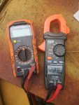
You'd check the current at M8 using your clamp on ammeter. The right meter in your pic.
Clamp it around ONE of the two wires going to M8. It doesn't matter which one.
Like this..
1726415304673.png
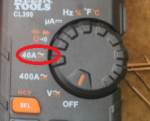
Set the meter to 40 AMP AC setting
1726414822869.png
Zero the meter is necessary.
Be sure the generators AM-VM switch is in the 3 0'clock position
Start the generator and close the contactor.
Apply your load.
See what current is read by the clamp on ammeter.

If zero try the following to see if the meter is burned out.
Turn off your loads.
Shut down the generator.
Install a jumper wire between the two terminals of M8.
Put the clamp on ammeter back on one of the wires to M8.
Zero the meter is necessary.
Start the generator and close the contactor.
Apply your load.
See what current is read by the clamp on ammeter.
If you now get a current reading of say 0.5 amps on your clamp on ammeter it would indicate M8 is burned out.
If still you don't get any current reading then you'll need to buzz out all the connections in my diagram above. (The middle section with M8 in the circuit.)
Turn off your loads.
Shut down the generator.
Remove the jumper wire installed across the towo terminals of M8.
 

jaybird67k

Member
60
20
8
Location
Texas
You'd check the current at M8 using your clamp on ammeter. The right meter in your pic.
Clamp it around ONE of the two wires going to M8. It doesn't matter which one.
Like this..
View attachment 931584
Set the meter to 40 AMP AC setting
View attachment 931583
Zero the meter is necessary.
Be sure the generators AM-VM switch is in the 3 0'clock position
Start the generator and close the contactor.
Apply your load.
See what current is read by the clamp on ammeter.

If zero try the following to see if the meter is burned out.
Turn off your loads.
Shut down the generator.
Install a jumper wire between the two terminals of M8.
Put the clamp on ammeter back on one of the wires to M8.
Zero the meter is necessary.
Start the generator and close the contactor.
Apply your load.
See what current is read by the clamp on ammeter.
If you now get a current reading of say 0.5 amps on your clamp on ammeter it would indicate M8 is burned out.
If still you don't get any current reading then you'll need to buzz out all the connections in my diagram above. (The middle section with M8 in the circuit.)
Turn off your loads.
Shut down the generator.
Remove the jumper wire installed across the towo terminals of M8.
Thanks a bunch. I'll let you know what I find.

Thanks, Jason
 
Top
AdBlock Detected

We get it, advertisements are annoying!

Sure, ad-blocking software does a great job at blocking ads, but it also blocks useful features of our website like our supporting vendors. Their ads help keep Steel Soldiers going. Please consider disabling your ad blockers for the site. Thanks!

I've Disabled AdBlock
No Thanks