• Steel Soldiers now has a few new forums, read more about it at: New Munitions Forums!

  • Microsoft MSN, Live, Hotmail, Outlook email users may not be receiving emails. We are working to resolve this issue. Please add support@steelsoldiers.com to your trusted contacts.

Radiator Fan ....... "turn off" Switch

Mogman

Moderator
Staff member
Moderator
Steel Soldiers Supporter
7,017
9,694
113
Location
Papalote, TX
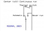
I would wire it to the thermal switch, short across the switch to never run, open the circuit to always run and complete the circuit to run automatically.
I can draw up a schematic tomorrow afternoon, going to the beach at 5am so I have to catch some ZZZZZ
 
Last edited:

Autonomy_Lost

Well-known member
687
1,537
93
Location
Pennsylvania
I would wire it to the thermal switch, short across the switch to never run, open the circuit to always run and complete the circuit to run automatically.
I can draw up a schematic tomorrow afternoon, going to the beach at 5am so I have to catch some ZZZZZ
That would work, but would still be susceptible to a TDM failure.
 

Mogman

Moderator
Staff member
Moderator
Steel Soldiers Supporter
7,017
9,694
113
Location
Papalote, TX
If you have manual control capabilities you could eliminate the TDM all together, want a schematic for that?
 

nikojo

Active member
Steel Soldiers Supporter
175
104
43
Location
Wisconsin and Illinois
If you have manual control capabilities you could eliminate the TDM all together, want a schematic for that?
YES! Please. I never understood the TDM from a fording standpoint as would think it might be difficult to 'time' the entry into water and may not be able to 'stomp' the accelerator to activate very easily

I also like the idea of getting rid of another failure point.

Also does it matter which part of TDM is the one that is wired??
 

Mogman

Moderator
Staff member
Moderator
Steel Soldiers Supporter
7,017
9,694
113
Location
Papalote, TX
YES! Please. I never understood the TDM from a fording standpoint as would think it might be difficult to 'time' the entry into water and may not be able to 'stomp' the accelerator to activate very easily

I also like the idea of getting rid of another failure point.

Also does it matter which part of TDM is the one that is wired??
Let me study it, I need to figure out if the temp switch is carrying the total current of the valve or if the TDM is acting like a relay, taking a smaller signal and amplifying it which would complicate things.
I think we should also move this to the mods forum where it actually belongs.
 

Autonomy_Lost

Well-known member
687
1,537
93
Location
Pennsylvania
It should be pretty simple. Output of the TDM is 2 wires, one should be ground and the other should toggle between 0 and 24v to control the cadillac valve.

If you interupt the latter wire it should make the fan turn on. Or inject 24v to make it turn off.
 

nikojo

Active member
Steel Soldiers Supporter
175
104
43
Location
Wisconsin and Illinois
Let me study it, I need to figure out if the temp switch is carrying the total current of the valve or if the TDM is acting like a relay, taking a smaller signal and amplifying it which would complicate things.
I think we should also move this to the mods forum where it actually belongs.
Agree. Can you move it to the mods forum for me?
 

FlameRed

Well-known member
Steel Soldiers Supporter
348
538
93
Location
Florida
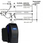
I figure I would post this in case someone like me wants to use a double pole rocker switch to manually control their fan clutch based on @Mogman excellent drawing.

Like Mogman indicated, I ran three 18 guages wires under one jacket into the cab.

I used a "Waterproof Rocker Switch Toggle On-Off-On 12V/20A 24V/10A 7Pin DPDT Blue LED Light" that is standard for rocker switch panels.

I was a bit picky, and wanted the middle position, normally called "off" to let the thermo switch on the engine to control the fan clutch. So I used a relay to enable this as shown.

On the drawing below:

  • Disconnect both packard connectors from the thermo switch and use a VOM to detmine which lead from the Cadillac valve has 24V present with the ignition on. This is the lead that needs to be "cut". Actually, I used extra packard connectors to build the leads so I could put the wiring back anytime in the future.
  • I am showing the back of the rocker switch. There are two rows of pins. With the switch oriented "up", the row on the left has 3 pins.
  • The middle pin in the left row needs to have the 12 or 24V+ (ignition) source.
  • The right row has four pins.
  • The upper pin on the right row is ground for the internal LED light on the switch.
  • The upper position of the switch activates "Continuous" engaged clutch. The upper led light on the switch will turn on.
  • The middle position of the switch, normally called "off" is Automatic mode, and lets the Thermo Switch on the engine. No light on the switch us illuminated.
  • The lower position of the switch is clutch "disengaged" mode. The bottom led light on the switch will turn on.
  • The pins are upside down, so when the switch is toggled up, the pins on the bottom make the circuit, and visa-versa. Use a VOM to verify.
  • You need a DPST 24 or 12V relay. Don't try to use a 24V relay if you are using 12V source as the relay probably will not work right.
  • If you have AC, you can tap into the AC on source, but use a diode to prevent a back feed to your AC systenm when you have the fan clutch switch in the upper position. Make sure the band on the diode is towards the switch, point away from your AC.
Hope this helps someone. Thanks to @Mogman for making the circuit function so clear (y)

Manual Fan Switch schematic.JPG
 

happyhapka

New member
9
0
1
Location
Idaho
nikojo, years back before I took the time to understand how the fan system worked ( and parts were less available) I wired in a DPDT switch to my truck that performs 3 functions. Always on, always off, or automatic (normal) mode. It's simple to do and all it takes is a couple of connections to the time delay relay 4 pin connection. I salvages a connector from an old Ford mustang in a salvage yard and wired it in. Works fine but is now left in AUTO mode since I fixed the fan.

frauhansen, just stomp on the accelerator and the switch on the side of the IP triggers the time delay relay to disconnect the fan for 10-20 seconds to allow the fan to freewheel when entering the water for fording. What I did was a hardwired version of that. Guten tag.


View attachment 888609
I really like that toggle idea you have, how did you wire it in and what wires did you use, do you have pictures or an easy guide, please help with this..


Thank you very much
 

happyhapka

New member
9
0
1
Location
Idaho
I figure I would post this in case someone like me wants to use a double pole rocker switch to manually control their fan clutch based on @Mogman excellent drawing.

Like Mogman indicated, I ran three 18 guages wires under one jacket into the cab.

I used a "Waterproof Rocker Switch Toggle On-Off-On 12V/20A 24V/10A 7Pin DPDT Blue LED Light" that is standard for rocker switch panels.

I was a bit picky, and wanted the middle position, normally called "off" to let the thermo switch on the engine to control the fan clutch. So I used a relay to enable this as shown.

On the drawing below:

  • Disconnect both packard connectors from the thermo switch and use a VOM to detmine which lead from the Cadillac valve has 24V present with the ignition on. This is the lead that needs to be "cut". Actually, I used extra packard connectors to build the leads so I could put the wiring back anytime in the future.
  • I am showing the back of the rocker switch. There are two rows of pins. With the switch oriented "up", the row on the left has 3 pins.
  • The middle pin in the left row needs to have the 12 or 24V+ (ignition) source.
  • The right row has four pins.
  • The upper pin on the right row is ground for the internal LED light on the switch.
  • The upper position of the switch activates "Continuous" engaged clutch. The upper led light on the switch will turn on.
  • The middle position of the switch, normally called "off" is Automatic mode, and lets the Thermo Switch on the engine. No light on the switch us illuminated.
  • The lower position of the switch is clutch "disengaged" mode. The bottom led light on the switch will turn on.
  • The pins are upside down, so when the switch is toggled up, the pins on the bottom make the circuit, and visa-versa. Use a VOM to verify.
  • You need a DPST 24 or 12V relay. Don't try to use a 24V relay if you are using 12V source as the relay probably will not work right.
  • If you have AC, you can tap into the AC on source, but use a diode to prevent a back feed to your AC systenm when you have the fan clutch switch in the upper position. Make sure the band on the diode is towards the switch, point away from your AC.
Hope this helps someone. Thanks to @Mogman for making the circuit function so clear (y)

View attachment 896983
This is great, so you spliced it at the thermoswitch and not at the 2 wire side of the cadilac....... why not at the 2 wire cadilac side? Just incase of a failure of some sort.

also where did you bring in the 12v source and the 24v source.. of the battery.
i dont have ac downstream of it.
Where did you get the 12v and 24v source? Did you get the 12v from the rear battery and the 24 from the front one? I dont have AC
 

FlameRed

Well-known member
Steel Soldiers Supporter
348
538
93
Location
Florida
Great information. Thank you for taking the time to post it up.

One question, why the AC
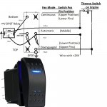
I was thinking that it might be good to have the engine fan run continuously when I had the AC on. After having installed this way for a few months, I found it unnecessary and disconnected the AC lead shown in that diagram. It just eats HP up when you do not necessary need to extra air flow. So, yeah, not really necessary at all! Do'oh on my part!

This is great, so you spliced it at the thermoswitch and not at the 2 wire side of the cadilac....... why not at the 2 wire cadilac side? Just incase of a failure of some sort.
At the time I thought it was easier for me to hook it to the thermoswitch. But I guess you could hook it up on the Cadillac Valve side of course.

Where did you get the 12v and 24v source? Did you get the 12v from the rear battery and the 24 from the front one? I dont have AC
There is +24V directly from one of the leads on the thermoswitch. The lead on the thermoswitch with +24v is the one you cut. The other lead you does not have +24V and that is the lead you do not touch in that diagram.

Instead of using a +12V ignition source, that I had readily accessible, just use a 24V DPST relay instead and use some +24V ignition source, like tap into the run position of the ignition switch instead. That would be easier. You want an ignition switched source so if you leave the switch in the wrong position when you shutdown the engine, it will not drain your battery. Do not hook it directly to the battery. And of course, add a fuse too to where you tap it from your ignition source.

You cannot use the +24V on the Thermoswitch as the +24V IGN source as at times that lead does not get power at all so when that happens this setup will not work properly. I think it cuts power if you floor the accelerator - Fording Mode? I have definitely seen no power to that circuit.

And just forget about that AC connection if you don't have AC - actually forget about it either way!


Manual Fan Switch schematic V2.jpg

Hope this helps.[/QUOTE]
 
Last edited:

happyhapka

New member
9
0
1
Location
Idaho
I was thinking that it might be good to have the engine fan run continuously when I had the AC on. After having installed this way for a few months, I found it unnecessary and disconnected the AC lead shown in that diagram. It just eats HP up when you do not necessary need to extra air flow. So, yeah, not really necessary at all! Do'oh on my part!


At the time I thought it was easier for me to hook it to the thermoswitch. But I guess you could hook it up on the Cadillac Valve side of course.


There is +24V directly from one of the leads on the thermoswitch. The lead on the thermoswitch with +24v is the one you cut. The other lead you does not have +24V and that is the lead you do not touch in that diagram.

Instead of using a +12V ignition source, that I had readily accessible, just use a 24V DPST relay instead and use some +24V ignition source, like tap into the run position of the ignition switch instead. That would be easier. You want an ignition switched source so if you leave the switch in the wrong position when you shutdown the engine, it will not drain your battery. Do not hook it directly to the battery. And of course, add a fuse too to where you tap it from your ignition source.

You cannot use the +24V on the Thermoswitch as the +24V IGN source as at times that lead does not get power at all so when that happens this setup will not work properly. I think it cuts power if you floor the accelerator - Fording Mode? I have definitely seen no power to that circuit.

And just forget about that AC connection if you don't have AC - actually forget about it either way!


View attachment 932327

Hope this helps.
[/QUOTE]
Whats a good 24v ignition source that is easy to plug into?
 

TOBASH

Father, Surgeon, Cantankerous Grouch
Steel Soldiers Supporter
Supporting Vendor
3,596
3,518
113
Location
Brooklyn, NY
Might be a great idea for towing uphill in the Summer. Loss of HP better than loss of engine block.
 

happyhapka

New member
9
0
1
Location
Idaho
I was thinking that it might be good to have the engine fan run continuously when I had the AC on. After having installed this way for a few months, I found it unnecessary and disconnected the AC lead shown in that diagram. It just eats HP up when you do not necessary need to extra air flow. So, yeah, not really necessary at all! Do'oh on my part!


At the time I thought it was easier for me to hook it to the thermoswitch. But I guess you could hook it up on the Cadillac Valve side of course.


There is +24V directly from one of the leads on the thermoswitch. The lead on the thermoswitch with +24v is the one you cut. The other lead you does not have +24V and that is the lead you do not touch in that diagram.

Instead of using a +12V ignition source, that I had readily accessible, just use a 24V DPST relay instead and use some +24V ignition source, like tap into the run position of the ignition switch instead. That would be easier. You want an ignition switched source so if you leave the switch in the wrong position when you shutdown the engine, it will not drain your battery. Do not hook it directly to the battery. And of course, add a fuse too to where you tap it from your ignition source.

You cannot use the +24V on the Thermoswitch as the +24V IGN source as at times that lead does not get power at all so when that happens this setup will not work properly. I think it cuts power if you floor the accelerator - Fording Mode? I have definitely seen no power to that circuit.

And just forget about that AC connection if you don't have AC - actually forget about it either way!


View attachment 932327

Hope this helps.
[/QUOTE]
What size fuse should i use? And i dont suppose you have a link to the relay i need?
 
Top
AdBlock Detected

We get it, advertisements are annoying!

Sure, ad-blocking software does a great job at blocking ads, but it also blocks useful features of our website like our supporting vendors. Their ads help keep Steel Soldiers going. Please consider disabling your ad blockers for the site. Thanks!

I've Disabled AdBlock
No Thanks