• Steel Soldiers now has a few new forums, read more about it at: New Munitions Forums!

  • Microsoft MSN, Live, Hotmail, Outlook email users may not be receiving emails. We are working to resolve this issue. Please add support@steelsoldiers.com to your trusted contacts.

TCM warm to the touch, No shift, Illumination light stays on

AKstewie

New member
8
1
3
Location
Alaska
I've been having a no shift limp mode with my 2010 Hmmwv N/A 4l80e.
So the the ole jumper wire trick and with the glow plug, plug in under the hood disconnected a steady light and no codes or flashing 12 shows up for the trans.

Upon throwing a used, but tested TCM at if from a guy same result. When changing out the TCM (mind you I'm in Alaska outside) the TCM coming out was warm to the touch! Not hot and no wires visibly damaged or melted.

Now the truck does go dead with new Optima's if left for a few days which indicates a draw or back feed.

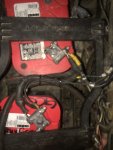
My thinking is when I put battery's in at the auction yard I didn't hook something up right causing a back feed or draw. Does any one have the battery compartment wiring numbers and what they go to, and is the trans hooked directly up to the battery to quiet down the power signal to the system?

It was a communications Hmmwv so Ill be pulling out the aftermarket attachments today and trying to jump a ground directly to the J2 E input.
 

Mogman

Moderator
Staff member
Moderator
Steel Soldiers Supporter
6,950
9,609
113
Location
Papalote, TX
Welcome to the SS forums.
I would never use an outside ground to J2E only A
It sounds like you have a power issue causing the drain on the batteries.
The TCM runs on 12V, that is one of the two factory connections to the positive of the rear battery (the other is to the regulator), the TCM has two 12V feeds, one continuous and one switched by a relay behind the commanders seat.
Normally if the switched power is "stuck" on the trans light will be on even with the truck run switch off.
Here is the trans. supplement, it has all the wiring information you need.
Until you can get into the diag mode with the jumper you cannot go forward with the troubleshooting of the trans
 

Attachments

AKstewie

New member
8
1
3
Location
Alaska
So I have that downloaded already and Ill be going through some of the tests today to narrow it down. The trans illumination light comes off with the main power so switched 12v is working. One of my questions is Id like to make sure everything in the battery compartment compartment is connected to spec as being the source of non running power to start off with. The wiring diagram doesn't give me a lay out of the battery compartment. Im fairly new to the forum and didnt find a diagram in the TM section. Diag work is nothing new to me, heady diesel tech of 20 years, just dont have some of the literature to go off of. I saw you post the PDF in another post and Im very thankful for your response and reaching out!
 

AKstewie

New member
8
1
3
Location
Alaska
If you by chance connected the 290/291/537 wire (page 141 of the supl) to the 24V tap in the battery box you more than likely have fried the TCM/TCMs
Everything on the shunt and the buss bar as is from the factory so none of that is tampered with. I have the 290 29 537 hooked to NEGatiVE on the bridged power R side battery, large 1920712 cable connected to the positive post left battery bridged power, 599 to shunt and 5072 to shunt
 
Last edited:

AKstewie

New member
8
1
3
Location
Alaska
So I have that downloaded already and Ill be going through some of the tests today to narrow it down. The trans illumination light comes off with the main power so switched 12v is working. One of my questions is Id like to make sure everything in the battery compartment compartment is connected to spec as being the source of non running power to start off with. The wiring diagram doesn't give me a lay out of the battery compartment. Im fairly new to the forum and didnt find a diagram in the TM section. Diag work is nothing new to me, heady diesel tech of 20 years, just dont have some of the literature to go off of. I saw you post the PDF in another post and Im very thankful for your response and reaching out!
ALSO page 53 it says to connect external power to the E pin on the J2 for diag I believe
 
Last edited:

Mogman

Moderator
Staff member
Moderator
Steel Soldiers Supporter
6,950
9,609
113
Location
Papalote, TX
So I have that downloaded already and Ill be going through some of the tests today to narrow it down. The trans illumination light comes off with the main power so switched 12v is working. One of my questions is Id like to make sure everything in the battery compartment compartment is connected to spec as being the source of non running power to start off with. The wiring diagram doesn't give me a lay out of the battery compartment. Im fairly new to the forum and didnt find a diagram in the TM section. Diag work is nothing new to me, heady diesel tech of 20 years, just dont have some of the literature to go off of. I saw you post the PDF in another post and Im very thankful for your response and reaching out!
Actually I forgot, the light is also feed by switched power so that does not mean switched power is also getting to the TCM although it sounds likely.
What model and serial is your HMMWV?
 

AKstewie

New member
8
1
3
Location
Alaska
2010 M1097R1 NA

WHen I did the wiring repairs in the auction yard I just copied what I found on a couple other hummers and the battery cables that didnt get clipped. But that was 3 months ago and Ive worked on 30 things since then. So just makin sure I got the source correct before I move forward is all? Seemd like a good start lol
 

Attachments

Last edited:

Mogman

Moderator
Staff member
Moderator
Steel Soldiers Supporter
6,950
9,609
113
Location
Papalote, TX
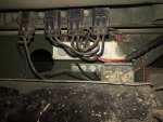
That looks correct although I am a little confused on what is going on on the far right side of the picture, it looks like both of the small 12v wires are connected together, there is one "extra" 12V wire, the wires should have tags with numbers on them, I see tags on some of them, the larger wire goes to the regulator to balance the battery charge.
You did not give me the serial number but I suspect it is a 57xxxx or 67xxxx if so here is the schematic that is closest to your truck.
 

Attachments

AKstewie

New member
8
1
3
Location
Alaska
That looks correct although I am a little confused on what is going on on the far right side of the picture, it looks like both of the small 12v wires are connected together, there is one "extra" 12V wire, the wires should have tags with numbers on them, I see tags on some of them, the larger wire goes to the regulator to balance the battery charge.
You did not give me the serial number but I suspect it is a 57xxxx or 67xxxx if so here is the schematic that is closest to your truck.
Its a 57 ser#, Small wires are numbered
That looks correct although I am a little confused on what is going on on the far right side of the picture, it looks like both of the small 12v wires are connected together, there is one "extra" 12V wire, the wires should have tags with numbers on them, I see tags on some of them, the larger wire goes to the regulator to balance the battery charge.
You did not give me the serial number but I suspect it is a 57xxxx or 67xxxx if so here is the schematic that is closest to your truck.
It’s a ser#57 truck. The one small wire is the 290/29/537 the other goes to a fuse and bus bar system for additional hardware as it was a coms truck. I’ll be pulling all of that out soon to hopefully eliminate the draw issue. In the first pic the fuse holder all the way on the left is that second 12v wire not marked. Even easier just gunna pull the fuses haha
 

Attachments

Last edited:

Mogman

Moderator
Staff member
Moderator
Steel Soldiers Supporter
6,950
9,609
113
Location
Papalote, TX
Its a 57 ser#, Small wires are numbered

It’s a ser#57 truck. The one small wire is the 290/29/537 the other goes to a fuse and bus bar system for additional hardware as it was a coms truck. I’ll be pulling all of that out soon to hopefully eliminate the draw issue. In the first pic the fuse holder all the way on the left is that second 12v wire not marked. Even easier just gunna pull the fuses haha
Most of the Comms were 24V
 

86humv

Well-known member
Steel Soldiers Supporter
1,704
504
113
Location
Texas
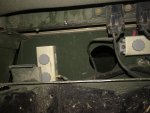
The relay in the panel behind batteries do fail on with ign. switch off.
If trans light works, and if relay fails on....light will be on with ign. switch off.
 
Top
AdBlock Detected

We get it, advertisements are annoying!

Sure, ad-blocking software does a great job at blocking ads, but it also blocks useful features of our website like our supporting vendors. Their ads help keep Steel Soldiers going. Please consider disabling your ad blockers for the site. Thanks!

I've Disabled AdBlock
No Thanks