• Steel Soldiers now has a few new forums, read more about it at: New Munitions Forums!

  • Microsoft MSN, Live, Hotmail, Outlook email users may not be receiving emails. We are working to resolve this issue. Please add support@steelsoldiers.com to your trusted contacts.

LMTV Frame twist

Ronmar

Well-known member
3,931
7,620
113
Location
Port angeles wa
Interesting thread read. Out of curiosity, how is the factory M1079 Van body attached?
4 anchor pockets(3x5”?) welded to the upper 6” frame channel near front and rear. The rear crane lift point is also incorporated into that upper channel just forward of the rear wheel. The box is attached to a box tube subframe that has 4 feet that rest in the pockets on 1/2” rubber pads. There is a large bolt hole down thru the middle of each foot/pocket. Two have nuts and bolts, the other two have long bolts with captive springs. I looked up what I thought was the spring specs once upon a time. If I recall correctly, they have a little over 2” of total compression @ ~1000#/in rate…

i bought a M1079 cab and chassis at auction. You can see the remnants of my pockets(cut the walls of the pockets off flush with the top of the frame) in this pic…
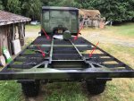
IMG_3927.jpeg
 
Last edited:

Mavcaster

Well-known member
203
422
63
Location
Maryland
4 anchor pockets(3x5”?) welded to the upper 6” frame channel near front and rear. The rear crane lift point is also incorporated into that upper channel just forward of the rear wheel. The box is attached to a box tube subframe that has 4 feet that rest in the pockets on 1/2” rubber pads. There is a large bolt hole down thru the middle of each foot/pocket. Two have nuts and bolts, the other two have long bolts with captive springs. I looked up what I thought was the spring specs once upon a time. If I recall correctly, they have a little over 2” of total compression @ ~1000#/in rate…

i bought a M1079 cab and chassis at auction. You can see the remnants of my pockets(cut the walls of the pockets off flush with the top of the frame) in this pic…

View attachment 937422
Ronmar it looks like here the large forward lifting cross member has been removed. Do you know if that part is solely for lifting or is it there for frame support as well?
 

Ronmar

Well-known member
3,931
7,620
113
Location
Port angeles wa
I don’t see it really supporting the frame all that muck as it is narrow and mounted perpendicular to it. Because the engine and trans is located there, trucks don’t typically have any re-enforcement there. Looking at it as a whole, it probably weakens more than it would support as they had to drill a lot of holes(6 in each frame rail) to bolt it in place with enough fastener shear to support most of the vehicle weight(its just forward of the CG) when lifting…
 

aw113sgte

Well-known member
Steel Soldiers Supporter
739
1,153
93
Location
La Crosse, WI
It will obviously strengthen that area, however it may also cause stress risers due to the increased stiffness. Crossmembers are needed and there is a large variation between FMTV models.
There will likely be more stress on bushings, but less stress on the frame.
 

Mavcaster

Well-known member
203
422
63
Location
Maryland
Yeah thanks Ronmar, I was considering removing mine but think I’ll just not go down that road. I saw a video awhile back where the controls for an electric hydro pump was mounted in one of the ends. Anyways I would need to fab another way to mount coolant res and cab leveling switch, etc


Sent from my iPhone using Tapatalk
 

Shakkles

New member
14
22
3
Location
IL
The wripling on the panels in this picture is my concern. Not sure whats going on here, but the seams look like they are separating...

I like the idea of composite for the clean panels, but don't want the added 'torsion' frame. for many of the reasons stated in this thread. height, torsion frame putting pressure where it wasn't designed to be.

i'm torn on what the right answer is and what direction i'm going to go. I've talked with several folks and looked at a lot of the designs, I just can't figure out how to keep the 'skin' clean and not wavy using metal.

I've think I've settled on my 'thermal transfer' solution for metal. Spray cork. Used in marine applications. I'm going to use it on the cab as well. Lots of good videos out there on this

Height and easy entry/exit are key design criteria. I don't know what it's called, but i'm calling it 'school bus entry'.
View attachment 937214
I don't see any "panel rippling" in that picture my man. I do see a lens flare artifact. Is that what you're seeing and thinking it's a physical defect on the truck or am i mistaken?
 
Last edited:

Ronmar

Well-known member
3,931
7,620
113
Location
Port angeles wa
Yeah thanks Ronmar, I was considering removing mine but think I’ll just not go down that road. I saw a video awhile back where the controls for an electric hydro pump was mounted in one of the ends. Anyways I would need to fab another way to mount coolant res and cab leveling switch, etc


Sent from my iPhone using Tapatalk
Well I needed the room for my habitat, so the cooling system and oil fills were getting re-engineered anyway. I actually wound up fabbing my own front wall truss that bolts in the same location, only down at the floor level, arching close over the top of the transmission. I even re-used the same lower cross-member channel. The original truss I welded to the back of the upper frame to extend the floor structure 18”:)

i designed my own cab suspension system using more commonly available bags and shocks, and relocated the height control valve down to the left frame right behind the power steering reservoir.
 
Last edited:
Top
AdBlock Detected

We get it, advertisements are annoying!

Sure, ad-blocking software does a great job at blocking ads, but it also blocks useful features of our website like our supporting vendors. Their ads help keep Steel Soldiers going. Please consider disabling your ad blockers for the site. Thanks!

I've Disabled AdBlock
No Thanks