• Steel Soldiers now has a few new forums, read more about it at: New Munitions Forums!

  • Microsoft MSN, Live, Hotmail, Outlook email users may not be receiving emails. We are working to resolve this issue. Please add support@steelsoldiers.com to your trusted contacts.

Retrofitting a 002 003 004 005 006 or 802 803 with a Generac Governor Controller Kit

peapvp

Well-known member
Steel Soldiers Supporter
1,139
1,294
113
Location
Basehor, KS
Quite a few years ago we had a customer in New Orleans with a 006A who had bought our Autostart Kit and had retrofitted the following
Generac Governor Controller Kit:

GENERAC 098647ASRV (98647) GOVERNOR CONTROL KIT, STEPPER
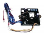
98647A.jpg

GENERAC G098290 - GOVERNOR STEPPER MOTOR
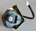
98290.jpg


Our customer posted a youtube video of this retrofit but I cannot find it.
The stepper motor is connected in place of the throttle cable

Both items can be purchased here:

Controller Kit


Stepper Motor

Installation Manual:
 

Attachments

rickf

Well-known member
Steel Soldiers Supporter
3,218
1,889
113
Location
Pemberton, N.J.
Nice, since my vernier function on my cable on my 002 has seized up it can be a pain to get the frequency set right. That might be an option.
 

peapvp

Well-known member
Steel Soldiers Supporter
1,139
1,294
113
Location
Basehor, KS
I found another video which shows the basic setup:

Note: the AC Voltage applied is around 12 VAC which would require the installation of a small AC Transformer to be installed
120VAC Pri
12VAC Sec
5VA


rickf

Well-known member
Steel Soldiers Supporter
3,218
1,889
113
Location
Pemberton, N.J.
Looking at the directions I see the controller needs 12 VDC and the frequency is controlled by the AC output. Where is the 12VAC needed?
 

peapvp

Well-known member
Steel Soldiers Supporter
1,139
1,294
113
Location
Basehor, KS
Looking at the directions I see the controller needs 12 VDC and the frequency is controlled by the AC output. Where is the 12VAC needed?
This is the feedback for the 60Hz to keep Genset at correct Frequency / rpm
I am not sure if this AC input can handle line voltage 120VAC or higher, hence line voltage would have to be stepped down
 

peapvp

Well-known member
Steel Soldiers Supporter
1,139
1,294
113
Location
Basehor, KS
Ask Generac?
Good Luck,
the fellow in the video had set his Heathkit Sine Square Audio Generator 1G-18 to ~ 60Hz and the highest output voltage as per Manual Page 60 is 10VAC rms
So we know for sure that the governor controller starts working at a very low AC Voltage on its sense inputs, but we do not know (at least I don't) of what the maximum permissible AC Voltage is for the sense input on the two blue wires.

My guess would be 120VAC + since this is Generac and they wouldn't add any extra parts like a small AC Transformer into their gensets in order to maximize their profits....
 

Attachments

peapvp

Well-known member
Steel Soldiers Supporter
1,139
1,294
113
Location
Basehor, KS
I agree. I think that in my experience Generac seems to be pretty parsimonious in their designs, subject to longevity design limitations.
Bingo!

The two Blue wires connect to the Hz / Frequency Gauge on the Genset

Now we just need to find out if Generac uses a Frequency Transducer which converts the 120 VAC to a DC Signal proportional to Frequency like the MEP's do or if they go directly with 120 VAC to their Frequency Gauges on their Gensets.

Controller Sensing Input Connection.jpg

This is part of the following manual:
 

Attachments

peapvp

Well-known member
Steel Soldiers Supporter
1,139
1,294
113
Location
Basehor, KS
@2Pbfeet

Found the answer here on redit


Did you check to make sure the governor controller is getting reference voltage for speed control. It uses voltage sensing off of the hz meter.

Brush replacement is common in these generac units. Without voltage, there will be zero governor actuation. Confirm that first, then if there's no output to the throttle, i would assume broken wire or bad connection, if not bad board.


Hey! Happy to have your help :)
There are 4 input wires on the governer controller. 1 red DC (12v power), 1 black DC (ground) and 2 blue AC wires.

I checked the governor controller input wires and got the following readings while the unit is running:

  1. Red DC wire is getting 12v DC
  2. Black DC wire (ground) is 0v DC
  3. Blue wires are both getting around 100+ V AC and climbing as the generator warms up from a cold start.
Is this what you mean by "reference" voltage? I assume that's the 12v DC I'm getting on the red wire. Or should I measure the blue wires while the unit is running with the meter set on something other than AC voltage?
 

Mullaney

Well-known member
Steel Soldiers Supporter
Supporting Vendor
7,829
20,020
113
Location
Charlotte NC
Bingo!

The two Blue wires connect to the Hz / Frequency Gauge on the Genset

Now we just need to find out if Generac uses a Frequency Transducer which converts the 120 VAC to a DC Signal proportional to Frequency like the MEP's do or if they go directly with 120 VAC to their Frequency Gauges on their Gensets.

View attachment 938805

This is part of the following manual:
.
Thanks for the book!
.
 

rickf

Well-known member
Steel Soldiers Supporter
3,218
1,889
113
Location
Pemberton, N.J.
But are the wires connected to the gauge output or the 110 input to the transducer? I am thinking that since this controller is designed to be used on a Generac set it would sense frequency from the 110 volt output of the genset. In out case the convenience outlet. I seriously doubt they use a screwy setup like the transducer used in our sets, I am think more along the lines of how a modern meter or Kill-a=Watt senses frequency.
 

peapvp

Well-known member
Steel Soldiers Supporter
1,139
1,294
113
Location
Basehor, KS
But are the wires connected to the gauge output or the 110 input to the transducer? I am thinking that since this controller is designed to be used on a Generac set it would sense frequency from the 110 volt output of the genset. In out case the convenience outlet. I seriously doubt they use a screwy setup like the transducer used in our sets, I am think more along the lines of how a modern meter or Kill-a=Watt senses frequency.
That’s correct. The sense input (two blue wires) connect directly to the 120 VAC of the genhead. The convenience outlet would be a good connection point.
I probably would add a 500mA 250V 3AG Fuse to the leg which connects to the phase with one of the two blue wires
 
Last edited:

peapvp

Well-known member
Steel Soldiers Supporter
1,139
1,294
113
Location
Basehor, KS
So, this leaves us only with the red and black wire. I would use a KuP relay with socket and drive the relay from anyone of the S1 switches on the contact for prime.
One Normally open contact is then connected to the red wire. The com contact gets a 16ga wire with a 5A 250V 3AG inline fuse and connects to the jumper connection on the batteries for 12 V fused supply.
The black wire connects on any ground stud in cubicle or to Genset frame.
The controller will then get 12V when S1 is in prime/run or prime/run/aux fuel or start

the final challenge would be the secure mounting of stepper motor and the connection to throttle / ip

I would propose a competition and each participant posts their install here on this thread. We collectively will select the winner.

The price will be a Autostart Kit from my Company for the winners Genset
 

2Pbfeet

Well-known member
493
930
93
Location
Mt. Hamilton, CA
That’s correct. The sense input (two blue wires) connect directly to the 120 VAC of the genhead. The convenience outlet would be a good connection point.
I probably would add a 500mA 250V 3AG Fuse to the leg which connects to the phase with one of the two blue wires
Perhaps a fuse and install it before the breaker for the convenience outlet so there isn't an accidental loss of signal? Loss of the AC signal mighty not be good.

All the best,

2Pbfeet
 

Chainbreaker

Well-known member
1,809
2,036
113
Location
Oregon
In the case of the MEP-002a/-003a and their fairly robust flyball governor setup the question that comes to my mind is... What added value would an electronic governor provide? Does that come into play somehow with an AutoStart kit?

Would the introduction of the "Generac Control Kit & Governor Stepper Motor" not introduce more potential failure points? Don't read this wrong... as I am typically in favor of retrofitting older mechanical failure prone/unreliable devices with modern solid-state devices when there is a clear benefit. Just trying to understand any potential trade-offs.
 

peapvp

Well-known member
Steel Soldiers Supporter
1,139
1,294
113
Location
Basehor, KS
In the case of the MEP-002a/-003a and their fairly robust flyball governor setup the question that comes to my mind is... What added value would an electronic governor provide? Does that come into play somehow with an AutoStart kit?

Would the introduction of the "Generac Control Kit & Governor Stepper Motor" not introduce more potential failure points? Don't read this wrong... as I am typically in favor of retrofitting older mechanical failure prone/unreliable devices with modern solid-state devices when there is a clear benefit. Just trying to understand any potential trade-offs.
To prevent drift primarily plus it will compensate frequency variations due to load changes.
This is not necessarily limited to Autostart operations, but when ever the Genset experiences a wider load change.
The utility versions become therefor more like precise units at a fraction of their cost
 
Top
AdBlock Detected

We get it, advertisements are annoying!

Sure, ad-blocking software does a great job at blocking ads, but it also blocks useful features of our website like our supporting vendors. Their ads help keep Steel Soldiers going. Please consider disabling your ad blockers for the site. Thanks!

I've Disabled AdBlock
No Thanks