• Steel Soldiers now has a few new forums, read more about it at: New Munitions Forums!

  • Microsoft MSN, Live, Hotmail, Outlook email users may not be receiving emails. We are working to resolve this issue. Please add support@steelsoldiers.com to your trusted contacts.

14V alternator harness..

Talns100

New member
8
0
1
Location
Israel
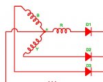
Hello, in the diagram shown below we can see a harness is connecting between the 14V stator and the regulator. It is also showing that the current is AC.
If this is the case and the regulator gets 14V AC why is there a rectifier connected to the stator?
The manual also says that the current is rectified so I don’t really get what is happening.
N1505 alternator + N3135 regulator

IMG_1469.png
 

Mogman

Moderator
Staff member
Moderator
Steel Soldiers Supporter
7,074
9,808
113
Location
Papalote, TX
That drawing is more representative than actual as the upper stator is not shown complete as there must be more rectifiers on the upper stator to produce DC, I assume the phased harness is used so the 14V source can be rectified and regulated independently from the 28V output.
It takes 6 diodes to form a 3 phase rectifier.
 
Last edited:

Talns100

New member
8
0
1
Location
Israel
That drawing is more representative than actual as the upper stator is not shown complete as there must be more rectifiers on the upper stator to produce DC, I assume the phased harness is used so the 14V source can be rectified and regulated independently from the 28V output.
It takes 6 diodes to form a 3 phase rectifier.
It seems the 14v source is rectified at the regulator and not in the alternator as they say in their manual.
What is actually going on?
 

Mogman

Moderator
Staff member
Moderator
Steel Soldiers Supporter
7,074
9,808
113
Location
Papalote, TX
This is what is "going on with the 28V stator, the diode drawn between the +28 output terminal and ground represents the 6 diode rectifier, if you use an ohm meter connected to the +28 output terminal and ground (the case) you will see conduction in one direction only just like the single diode drawn in the docs.
On the 14V side they are likely using SCRs in the rectifier instead of plain diodes to independently regulate the 14V tap, let me see if I can find a schematic of how that would look.
Here is an example of what is going on in the 28V circuit with the 6 diode rectifier being represented by the single diode.
alt.JPG
The field in these alternators do not have slip rings and brushes as shown in this schematic.
 

Mogman

Moderator
Staff member
Moderator
Steel Soldiers Supporter
7,074
9,808
113
Location
Papalote, TX
This is probably close to what is going on with the 14V side of the alt
On the 28V side the reg controls the field winding to control the 28V output on the 14V side it uses SCRs (or something similar) to regulate the 14V output independent of the 28V output.
The phase cable takes the three phase stator output to the regulator where it rectifies it and controls the voltage inside the regulator itself.
It does this by basically turning on and off the SCRs to control the 14V output.
This type of scheme is by far the most efficient way to regulate a three phase output, much more efficient than using a linear regulator after rectification.
An SCR is basically a diode that you can control using its third lead and are the three rectifiers in the bottom of the schematic.
SRC.JPG
 
Last edited:
Top
AdBlock Detected

We get it, advertisements are annoying!

Sure, ad-blocking software does a great job at blocking ads, but it also blocks useful features of our website like our supporting vendors. Their ads help keep Steel Soldiers going. Please consider disabling your ad blockers for the site. Thanks!

I've Disabled AdBlock
No Thanks