• Steel Soldiers now has a few new forums, read more about it at: New Munitions Forums!

  • Microsoft MSN, Live, Hotmail, Outlook email users may not be receiving emails. We are working to resolve this issue. Please add support@steelsoldiers.com to your trusted contacts.

303M HydraMatic rebuild

G744

Well-known member
Steel Soldiers Supporter
1,733
3,914
113
Location
Hidden Valley, Az
Nice dedicated effort making those old transmissions work again.

Years ago, I inherited a M211 with no power pak, so I retrofitted a Caddy 501 V8 and a turbo-400 with the extra low first gear. I'd seen it done on several used in field harvesting. Mine worked fine both on and off road, but sure was a thirsty beast...
 

rustystud

Well-known member
9,320
3,140
113
Location
Woodinville, Washington
Let us know how this goes rusty-the making of parts. I would be interested in purchasing some parts for my own rat-holing. With some of these harder to find components it would be nice to solve this problem.
Admittedly, the couple auto transmissions I have overhauled have been during an era of GM making the same thing for many years and parts abundance everywhere. That being said, I would usually buy a new front pump, just out of ease. Besides the vanes in the front pump, how does the rotor usually fare through the rebuild process? Is there any other parts for the front pump back within specifications.

On the rear pump you had mentioned it would take an arm and a leg to have it machined. Will it work as well as it should with it being hogged out like that? It looks pretty substantial. Could a person machine out a small amount of the cast iron and build a steel sleeve to press into the cast housing to bring it back into spec?

I need to go a re-read everything and look at the pics.

Also, while I am thinking of it, how do you typically clean up your cases. They look nice and spot less-on the outer portion I would mean. I know with auto trannys "cleanliness if next to godlyness" but I was curious how you clean the other portion beings its cast iron and not aluminum.
I have been thinking about ways to fix the rear pump. The steel sleeve idea is a good one. The only problem is finding the "center" of the "Gerotor's" outer ring. The center part fits on the output shaft, but the outer ring is "offset" . Finding the proper offset and aligning it with the output and input holes would be a real challenge.
As far as how do I clean my parts, well I have a 40 gallon parts washer, plus lots of Brake Klean. That combined with steel wire brushes and lots of "elbow grease" gets them pretty clean. For the rusty parts I have a nice sandblaster .
 

rustystud

Well-known member
9,320
3,140
113
Location
Woodinville, Washington
Nice dedicated effort making those old transmissions work again.

Years ago, I inherited a M211 with no power pak, so I retrofitted a Caddy 501 V8 and a turbo-400 with the extra low first gear. I'd seen it done on several used in field harvesting. Mine worked fine both on and off road, but sure was a thirsty beast...
I put a 500 Caddy and TH400 into my old CUCV truck. Sold it to the neighbor boy (18yrs old) who promptly drove it into the ground. I told him NOT to over-rev it, but he didn't listen.
 

G744

Well-known member
Steel Soldiers Supporter
1,733
3,914
113
Location
Hidden Valley, Az
Yep, that Caddy motor made plenty torque under 4K RPM, and that didn't bother it at all.

Lots of reciprocating mass there...

D
 

jeffhuey1n

SMSgt, USAF (Ret.)
Steel Soldiers Supporter
1,906
1,514
113
Location
Laramie County, Wyoming
Great thread, add me to any new posts. One of these days I might tackle pulling the transmission from one of my M211’s. I suspect it’s locked up because all the drive shafts are disconnected and are hanging in place with cargo straps.
Now to find the time…
 

rustystud

Well-known member
9,320
3,140
113
Location
Woodinville, Washington
I haven't posted much lately partly to being sick, but mostly I'm waiting on the machinist to finish some parts I'm having him make for me.
So I've been cleaning and sorting out parts. What to keep and what to throw away.
Here is a shift valve I cleaned today. As you can plainly see it is junk. The rust has eaten into the machined "land" so it will never seal properly again. The fluid will leak by causing strange shifts. Not good.
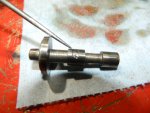
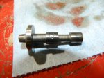
048.JPG047.JPG
I ended up with half the valves in this valve body being trash. I was able to save the aluminum bodies though.
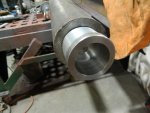
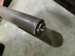
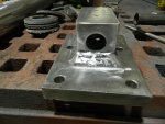
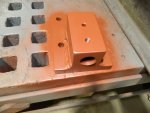
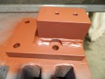
With all this down time I would love to start the second 303M build but I need the transmission holder. I am building a new holder that will handle over 1000 Ibs of weight. Again, the machinist is machining out the bore in the 2.5" X 2.5" block of steel that will get welded to the 1.25" thick x 6" x 8" plate.
Also the new Jib crane I'm building needs several items machined. So I'm stuck for now.
I still have four more transmissions to tear down, though I'm getting tired of cleaning parts right now.
I need a "hot tank" soon. Again it needs to be built by me. I will be making it out of stainless steel. I hate rust !!!!
So I'm cleaning parts and showing you all what to look for.
I am making a new oil pump pickup tube for my "gear" front pump. The gear pumps have the intake port standing straight up instead of at a 20-degree angle. The intake pipe is also 3/4" instead of 5/8" so an adapter will need to be welded on.
032.JPG033.JPG I cut up a junk oil pan housing to facilitate making the intake pipe.

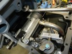
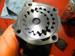
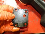
There is one other thing I will show you today. The rear pump (not the reduction pump) on the 303M transmission does not make any pressure. It is dumped out. Why they did this I do not know. I'm trying to figure out how to adapt a civilian pump to the 303M transmission to increase fluid volume.
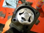
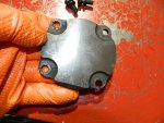
035.JPG036.JPG This is the 303M pump. You can see it is a small Gerotor style pump with a hole in the cover to drop the fluid. You can also see the outer ring is allowed to "float" in it's bore just like the reduction pump does. Very bad design.
034.JPG037.JPG This is a pump out of a 1955 Cadilliac HydraMatic.
It uses a crescent gear pump design. Extremely efficient for pressure systems.
 

Jbulach

Well-known member
Steel Soldiers Supporter
2,686
2,244
113
Location
Sunman Indiana
…There is one other thing I will show you today. The rear pump (not the reduction pump) on the 303M transmission does not make any pressure. It is dumped out. Why they did this I do not know. I'm trying to figure out how to adapt a civilian pump to the 303M transmission to increase fluid volume.
View attachment 938278View attachment 938279 This is the 303M pump. You can see it is a small Gerotor style pump with a hole in the cover to drop the fluid…
Any chance they are just using that pump as a scavenge pump to move fluid up from a low point in the trans or reduction unit to where one of the other pumps can pick it up? Sorry, I know nothing about these transmissions other than what you’re showing us… Happy new year and hope you’re feeling better!
 

rustystud

Well-known member
9,320
3,140
113
Location
Woodinville, Washington
Any chance they are just using that pump as a scavenge pump to move fluid up from a low point in the trans or reduction unit to where one of the other pumps can pick it up? Sorry, I know nothing about these transmissions other than what you’re showing us… Happy new year and hope you’re feeling better!
They actually do have the pump suck fluid out of the reduction area though it is not really needed. The real reason they keep the pump is for the "governor" assembly. The pump is just an afterthought.
But with our transmissions being so old and worn out now, the extra fluid would help tremendously.
 

rustystud

Well-known member
9,320
3,140
113
Location
Woodinville, Washington
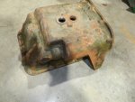
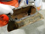
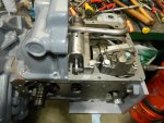
Today I tore down the oil pan from the last 303M transmission I brought in a few weeks ago. Since it is such a pain to completely tear down a 303M transmission I usually take it in sections. The oil pan comes off and is set aside as is the reduction housing. Later I come back and finish the tear down.
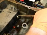
This particular oil pan was a real pain in the buttock's to disassemble. So I decided to show you how I remove the cooler without damaging it.
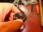
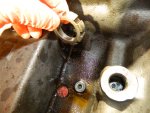
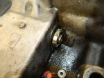
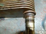
The trick is to remove the special nuts with a spanner wrench, then reinstall the one by the filter with the nut reversed. This gives you more threads since there is a recess built into the nut. Install the nut with a 1/4" gap. Then using a drift punch hammer the nut until the filter comes loose. You will need to alternate between the nuts. The one nut will not come off of course, so you just loosen it until you have a 1/4" gap then hammer away. When the nuts touch the housing, you just loosen them up again and hammer away.
Once the cooler is flush with the housing you can "gently" pry it with a small pry bar. Usually by this time the cooler will come out.

001.JPG Here you can see the recess in the nut.
002.JPG003.JPG Reinstall the nut backwards leaving a 1/4" gap.
004.JPG Using a drift punch hammer the nut. Be careful to not hit the cooler tube !
Alternate between the two nuts.
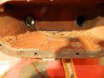
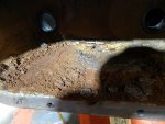
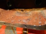
005.JPG007.JPG008.JPG Here you can see how dirty this unit was. I recommend everyone who has this transmission to add a coolant filter to the oil pan inlet.
This oil pan was filled completely with gunk under the cooler. There was no coolant circulation around this cooler at all. In fact, I had to use a screwdriver to remove the hardened gunk before the cooler could come out.
 

rustystud

Well-known member
9,320
3,140
113
Location
Woodinville, Washington
I thought I should let people know what spanner wrench I use. It's the "Blue Point AHS300B" spanner wrench. You can buy new ones on eBay for just $34.00 . I have several as this is my favorite spanner. It is small enough to reach tight places, yet strong enough to take a hit from a hammer.
 

DUUANE

Active member
Steel Soldiers Supporter
459
222
43
Location
Qualicum Beach BC
Reinstall the nut backwards leaving a 1/4" gap

These tips are so handy with a seldom done critical task. Having the hand of experience guide you in uncharted territory fiddling with fragile part dissasembly saves the job in many situations.

Thanks Rusty! (y)
 

rustystud

Well-known member
9,320
3,140
113
Location
Woodinville, Washington
Reinstall the nut backwards leaving a 1/4" gap

These tips are so handy with a seldom done critical task. Having the hand of experience guide you in uncharted territory fiddling with fragile part dissasembly saves the job in many situations.

Thanks Rusty! (y)
I almost didn't post that tip. I had already loosened the cooler and was going to remove it when I thought someone might come across another stuck cooler. Since these parts are becoming as scarce as "hens teeth" you don't want to damage your cooler. So I posted the tip.
 

rustystud

Well-known member
9,320
3,140
113
Location
Woodinville, Washington
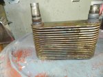
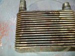
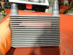
I finished cleaning the oil cooler and oil cooler housing. Since "1944mb" from Montana asked how I clean my parts I thought I would show you a little bit of the process.
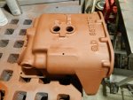
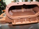
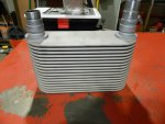
First, all parts have the outside crud removed and then degreased. Once that is done, I usually dissemble whatever part or unit I'm working on. Then it's into the parts washer for a good scrubbing. If there is rust or old paint that needs removing it goes into the sandblaster. All external cast-iron parts then get a going over with the metal grinder to remove all sharp edges and over-casting. I like a good clean look in my transmissions. Then all external parts get painted.

001.JPG002.JPG This housing has been cleaned in the parts washer.
004.JPG005.JPG006.JPGThe cooler has been cleaned in the parts washer.

011.JPG012.JPG I forgot to take pictures of the sandblasted housing but here it is after the primer was applied.

009.JPG010.JPG Here's the cooler after sandblasting. You must be very careful to close-off the tubes. No blast media must be allowed to get inside the cooler.
That's pretty much how I clean up large items.
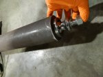
Now for smaller and more delicate items I have several large "sonic" cleaners that do a great job.
 
Last edited:

rustystud

Well-known member
9,320
3,140
113
Location
Woodinville, Washington
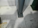
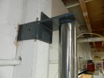
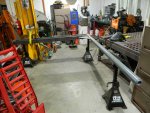
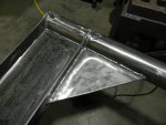
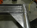
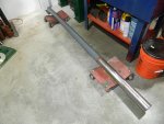
I see it's been a few days since I posted anything new, so I decided to show you how my transmission holder is coming along and the new Jib crane.

025.JPG026.JPG028.JPG037.JPG031.JPG032.JPG038.JPG041.JPG053.JPG054.JPG061.JPG062.JPG071.JPG072.JPG074.JPG075.JPG
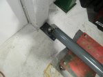
I had to prefit the column to get the upper bracket in position and the lower end mounted into the concrete so the column would be straight up and down.
Then I took it down and welded the "I" beam in place. I still need to mount the whole assembly, but I need to figure out how to pull it up into position. Especially since I'm doing all this by myself.

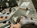
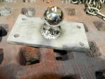
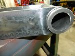
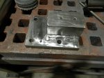
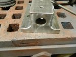
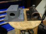
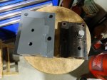
Next is pictures of the new transmission mount.
045.JPG046.JPG048.JPG056.JPG057.JPG065.JPG066.JPG
You can see the difference between the factory "cast iron" mount and the new mount made out of steel.
The factory mount could hold 300 Ibs. I figure this new mount can easily hold 1000 Ibs.
 

Mullaney

Well-known member
Steel Soldiers Supporter
Supporting Vendor
7,880
20,124
113
Location
Charlotte NC
I see it's been a few days since I posted anything new, so I decided to show you how my transmission holder is coming along and the new Jib crane.

View attachment 939616View attachment 939617View attachment 939618View attachment 939619View attachment 939620View attachment 939621View attachment 939622View attachment 939623View attachment 939624View attachment 939625View attachment 939626View attachment 939627View attachment 939628View attachment 939629View attachment 939630View attachment 939631
I had to prefit the column to get the upper bracket in position and the lower end mounted into the concrete so the column would be straight up and down.
Then I took it down and welded the "I" beam in place. I still need to mount the whole assembly, but I need to figure out how to pull it up into position. Especially since I'm doing all this by myself.

Next is pictures of the new transmission mount.
View attachment 939634View attachment 939635View attachment 939636View attachment 939632View attachment 939633View attachment 939637View attachment 939638
You can see the difference between the factory "cast iron" mount and the new mount made out of steel.
The factory mount could hold 300 Ibs. I figure this new mount can easily hold 1000 Ibs.
.
Nice looking welds...
 

DUUANE

Active member
Steel Soldiers Supporter
459
222
43
Location
Qualicum Beach BC
I see it's been a few days since I posted anything new, so I decided to show you how my transmission holder is coming along and the new Jib crane.

View attachment 939616View attachment 939617View attachment 939618View attachment 939619View attachment 939620View attachment 939621View attachment 939622View attachment 939623View attachment 939624View attachment 939625View attachment 939626View attachment 939627View attachment 939628View attachment 939629View attachment 939630View attachment 939631
I had to prefit the column to get the upper bracket in position and the lower end mounted into the concrete so the column would be straight up and down.
Then I took it down and welded the "I" beam in place. I still need to mount the whole assembly, but I need to figure out how to pull it up into position. Especially since I'm doing all this by myself.

Next is pictures of the new transmission mount.
View attachment 939634View attachment 939635View attachment 939636View attachment 939632View attachment 939633View attachment 939637View attachment 939638
You can see the difference between the factory "cast iron" mount and the new mount made out of steel.
The factory mount could hold 300 Ibs. I figure this new mount can easily hold 1000 Ibs.

Great work, looks fabulous.(y)
 
Top
AdBlock Detected

We get it, advertisements are annoying!

Sure, ad-blocking software does a great job at blocking ads, but it also blocks useful features of our website like our supporting vendors. Their ads help keep Steel Soldiers going. Please consider disabling your ad blockers for the site. Thanks!

I've Disabled AdBlock
No Thanks