Well my search for some machine shop to help fabricate the throttle lever shafts has proven futile.
Unless I want 1000 units or more, most shops don't even want to talk with me.
So that leaves me with using shafts from civilian HydraMatics. The problem there is, they too have a tendency to get broken ! Thou not as often as the 303M does.
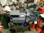
I started tearing down the "governor" - "reverse blocker" units. The reverse pistons all had gunk behind them, so it's a good idea for anyone rebuilding their 303M Hydros to clean this unit well.

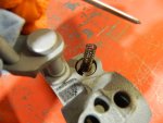
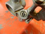
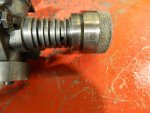
You first need to cut off the "pin" that holds in the reverse blocker piston and spring. Later you can use a 16d finish nail to go back in.
Remove the piston and spring (the spring will shoot out after you remove the pin so watch out).

Then you will need to clean-up the governor bore. I use a "brake cylinder hone" for this.


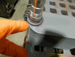
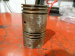
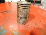
You need to remove all grooves from previous rings. Aligning this part is very critical for the longevity of the transmission, as it involves governor pressure. If the reverse blocker unit is not aligned correctly it will cause heavy grooving in the governor bore.


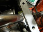
These two pictures show how the rings dug into the one side of the bore. This was after I honed it out too ! This unit had not been aligned correctly.
Putting a heavily grooved unit back in service can cause the new governor rings to break. Or the very least to leak severely.

Like I said earlier, you can use a 16d finish nail. Just cut and hammer the one end.

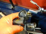
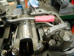
You might be wondering what the reverse blocker actually does. Here's a picture that shows how the blocker really "blocks" the manual valve from moving out of reverse.

The reverse piston when applied moves out of its bore to physically engage the lever which in turn blocks the manual valve.
In this picture you can also see I have installed the three tubes connecting the valve body to the reverse blocker assembly.
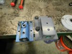
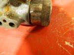
Just for grins and giggles I want to show you how the military valve body differs from a civilian unit.
The military valve body has a steel insert in the manual valve lever bore. This strengthens the housing while providing a solid surface for the shift lever to operate against. The Cadilliac HydraMatic also use's a Bronze bushing here, but the steel one is better for this application as it's support for the aluminum housing is far superior.

Later I will show the valve body going together and show you how to align the reverse blocker assembly.