• Steel Soldiers now has a few new forums, read more about it at: New Munitions Forums!

  • Microsoft MSN, Live, Hotmail, Outlook email users may not be receiving emails. We are working to resolve this issue. Please add support@steelsoldiers.com to your trusted contacts.

Voltage Regulator replacement

Dog Breath

Member
Steel Soldiers Supporter
59
83
18
Location
Wisconsin
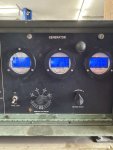
I Had a high AC voltage issue with my 003a after resurrecting it from the scrap heap, so i contacted @KKlop (member here) and within days of ordering the VR it was at my house..Now my 003 is back to normal for voltage putting out 236vac on l1-l3. Now i cannot get gauge m4 or m5 to work..I tested the ac voltage going into the transducer and it was 136vac. does that sound right..I do have digital frequecy and volt/lamp gauges from xtreme kreations gauge co. but i cannot find the directions. Does that name ring a bell with anyone here? On the box the name is James Caruso. i am assuming these gauges are from years ago.. I am a mechanic with limited AC electrical knowledge so any help figuring out how to get m4/m5 gauges working again would be great
 

Scoobyshep

Well-known member
1,239
1,789
113
Location
Florida
I Had a high AC voltage issue with my 003a after resurrecting it from the scrap heap, so i contacted @KKlop (member here) and within days of ordering the VR it was at my house..Now my 003 is back to normal for voltage putting out 236vac on l1-l3. Now i cannot get gauge m4 or m5 to work..I tested the ac voltage going into the transducer and it was 136vac. does that sound right..I do have digital frequecy and volt/lamp gauges from xtreme kreations gauge co. but i cannot find the directions. Does that name ring a bell with anyone here? On the box the name is James Caruso. i am assuming these gauges are from years ago.. I am a mechanic with limited AC electrical knowledge so any help figuring out how to get m4/m5 gauges working again would be great
Before you dig into m4 and M5 any deeper make sure the selector switch is in the correct position if the generator is set up for single phase and you're in one of the three phase positions these meters will not work
 

Dog Breath

Member
Steel Soldiers Supporter
59
83
18
Location
Wisconsin
Switches are in correct positions. L1-L3 phase1 . Getting proper ac voltage on multi meter but gauge isn’t moving. Can I hook digital gauge to the wires going to m5?
 

Scoobyshep

Well-known member
1,239
1,789
113
Location
Florida
Switches are in correct positions. L1-L3 phase1 . Getting proper ac voltage on multi meter but gauge isn’t moving. Can I hook digital gauge to the wires going to m5?
In that case yes you have a bad meter, yes you can hook an aftermarket meter to those feeds. Be sure the new meter is rated for the voltage applied
 

kloppk

Well-known member
Steel Soldiers Supporter
2,213
3,793
113
Location
Pepperell, Massachusetts
I have an extra transformer. I’m not by my gen but it’s on the back top of the control box. Ac in dc out?
It's AC current "in" by way of the wires passing through each CT opening. They created a magnetic field that the coils inside the CT detect creating an AC current output. The AC output current is proportional to the current in the leads passing through the CT openings.

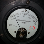
The Percent Load Meter is an ammeter, not a voltmeter.
When 1 amp of AC current is flowing through the meter it will read 133%
One can tell it's an ammeter by looking at the printing on the face of the meter circled in red.
The "FS=1 A AC" indicates the Full Scale (FS) deflection requires 1 amp of AC current.
1738422031949.png
 
Last edited:

Dog Breath

Member
Steel Soldiers Supporter
59
83
18
Location
Wisconsin
I am struggling with this ammeter. I took off the box with the main lugs and checked all the connections on the ct, rotary switch etc. i found a loose connection on the main breaker and a couple other connections that i tweeked. From where does the ammeter pick up its signal? from the CT but what can i test before i put this back together
 

kloppk

Well-known member
Steel Soldiers Supporter
2,213
3,793
113
Location
Pepperell, Massachusetts
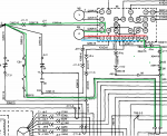
When in single phase mode only CT1-C is used to drive the %Current Meter.
The path highlighted in GREEN shows the paths from CT1-C to M4.
The last leg of the connection are the RED and BLUE lines. These are the connections made internal to S8 depending on if S8 is in 1 Phase L3-L1 or 1 Phase L3-L0. Changing the switch between those two positions only affects how the voltmeter is connected but keep M4 electrically connected the same way. Terminals 56 and 57 are tied together.

You may want to do some continuity tests around the green loop and the blue and red to make sure there is continuity.
Also to check continuity of the CT itself in case it failed.


1738428204827.png
 

Dog Breath

Member
Steel Soldiers Supporter
59
83
18
Location
Wisconsin
This sounds like your Frequency transducer for your Hz gage, not a transformer for the ammeter.
Yes I figured that out this morning. And the Ct I suspect is for the ammeter/percentage meter. I am getting a crash course in electronics. I can change an outlet but anything more is Greek to me. I did follow the electrical schematics from kloppk and trouble shot the control box. I suspect my ct went south
 
Top
AdBlock Detected

We get it, advertisements are annoying!

Sure, ad-blocking software does a great job at blocking ads, but it also blocks useful features of our website like our supporting vendors. Their ads help keep Steel Soldiers going. Please consider disabling your ad blockers for the site. Thanks!

I've Disabled AdBlock
No Thanks