• Steel Soldiers now has a few new forums, read more about it at: New Munitions Forums!

  • Microsoft MSN, Live, Hotmail, Outlook email users may not be receiving emails. We are working to resolve this issue. Please add support@steelsoldiers.com to your trusted contacts.

Peter Bog's CAD deuce schematic!

Recovry4x4

LLM/Member 785
Super Moderator
Steel Soldiers Supporter
34,012
1,808
113
Location
GA Mountains
Hey Gang, a while back member Peter Bog did a fabulous CAD workup of the deuce wiring schematic. He sent many of us copies at the cost of shipping. Some of you got the file emailed to you. If anyone has this file can you email it to magnus580 or let him or I know you have it so he can get a copy? Hey Robert Miller, don't you have the file?
Kenny
 

SixBuy

New member
226
1
0
Location
Dallas/Texas
PB,
Sorry for the delay - just got back in town. The errors were just little stuff, you know, the kind of stuff that drives perfectionists craz(ier). LOL But since you asked ...

1) The '491 - park' circuit is labeled '191...' just under the 'Air Activated Stoplight Switch...'
2) The switch pole circle on terminal 'B' of the ignition switch is missing (Really Big Deal!)
3) It appears the innards of the Starter Solenoid are somehow reversed - activating the Magnetic Start Relay and the Starter Solenoid would produce a dead short across the battery. My guess is maybe it's drawn upside down in the Solenoid?

All just minor stuff compared to the net worth of what you've done. I hope you don't mind that I've passed on copies to others.

A really neat addition would be to stick a bulb number chart in some unused space at the bottom... See? Give them an inch...

Thanks again!
 
Just wanted to send a Big "ATTA-BOY" to everyone involved with this thread.

First, to Peter Bog, for the outstanding conversion of the schematic to AutoCAD. Next, to Kenny (R4x4), for reviving the topic; to Robert (RDM) for submitting the files; and to Mike (m580), for . . . well, for everything he does to keep us going.

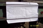
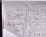
I used the big plotter at work to print a huge (D size) sheet. (shhh, . . . don't tell the boss!) I took the liberty to change the colors to Black, OD, and Tan to give it a more military look.

I found some long narrow flexible magnets that I had laying around (salvaged from a refrigerator door gasket) that work great for temporarily hanging the schematic on the truck.

I also gave it a quick "lamination" with some leftover adhesive-backed clear plastic film. (also something I had laying around - it's the stuff you get at the hardware store to protect the carpet in your home.)

Thanks again.
 

Attachments

OPCOM

Moderator
Steel Soldiers Supporter
3,657
27
48
Location
Dallas, Texas
BTW I think there is a mistake on the bendix. The way the wires are drawn, terminals 1 and 4 in the schematic should be the coil and terminals 2 and 3 should be the contactor. Does anyone else notice this?
 

mudguppy

New member
1,587
15
0
Location
duncan, sc
ok, so i downloaded the cad drawings and made a few of the recommended changes:

starter - flipped coil and contacts
added circuit breaker to light switch
changed color to green
renamed "Switch Ignition" as "Master Switch"
changed heater feed "35" to read "55"

attached is the PDF version. aaaaaaannnnd i'm having trouble getting the .dwg uploaded, even zipped as a .zip file.

what's the secret?
 

Attachments

cranetruck

Moderator
Super Moderator
Steel Soldiers Supporter
10,350
75
48
Location
Meadows of Dan, Virginia
Travis, the light switch CB is within the switch housing......it's rated 20 amps and the dimmer resistor is 30 ohms.

Thanks for working on it, although I'm personally perfectly happy with the TM wiring diagrams, with all the variations from year to year. Some features like an oil pressure safety switch is not present on all models. Wiring, specific for other variants should be so labeled.
All a pretty big job if it's to be useful.
I also find it interesting to see changes as they occur in time, where does the push button switch come in and how is its wiring to be shown.

What's not well documented are the ground returns, they should be labeled exactly the way they are realized on the vehicle, such as "ground" strap, "washer/screw","housing" etc, so that the return path to battery neg terminal can be followed in the diagram. Some diagrams show a little of this ground wiring some don't.
All light bulb part numbers should also be shown with wattage and/or current drain.
The turn signal pilot light should be grounded, the instrument panel grounding should be made clear....it goes on and on.

Edit: Added a sentence.
 
Last edited:

mudguppy

New member
1,587
15
0
Location
duncan, sc
i can do it - just going to need some help w/ "correct" changes (such as the grounding types, bulb #'s, and other things that you suggested).

does the TM dwg of the rotary switch benefit over Peter's switch dwg? to me it seems that the switch drawn gives a more legible depiction of the switch function contacts - but if there's another reason it could be adopted.

regardless of switch diagram, i would be interested in the grounding methods and bulb numbers and such, however. so if someone wanted to help with that stuff i'd be happy to make the changes.
 

Peter Bog

New member
19
0
0
Location
longisland
I add some of the comments that cranetruck put down and a revision box in.
If any body wants to do the revisons send me a email and I will send out the Dwg.. the orignal size of the pdf is 22"x36"

pete
 

Attachments

cranetruck

Moderator
Super Moderator
Steel Soldiers Supporter
10,350
75
48
Location
Meadows of Dan, Virginia
i offered to do the same and made / provided as many modifications as given direction to do. the other outstanding issues / corrections were still not addressed due to lack of direction at the time through current.

point: there are still updates that need to be made but none have stepped forward to instruct.
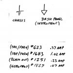
I'd like to see the simplified version of the light switch as shown below and separate the ground at the instrument panel to show that the instruments are together grounded via the 1/4 turn fasternes to "chassis".
The bulb info below would be useful...

The fuel level sending unit is grounded to the tank and then via wire #79 to "chassis", a note would be helpful as well to the effect "Full: 30 Ohms, Empty: 0 Ohms".

About grounding in general, may I humbly refer you all to Military Vehicles Magazine issue #122, Aug 2007 for info (article by yours truly). Reading it should make it very clear that the ground symbol is not always an indication of a direct path to the battery (NEG) terminal.
 

Attachments

mudguppy

New member
1,587
15
0
Location
duncan, sc
Bjorn,

i'm working on these final corrections now. i believe that i follow your bulb numbers except for the BO: are the BO tail and stop and front BO markers all the same #?

also, i thought at one point you gave me info on the head light bulbs but cannot find that...?
 

cranetruck

Moderator
Super Moderator
Steel Soldiers Supporter
10,350
75
48
Location
Meadows of Dan, Virginia
Bjorn,

i'm working on these final corrections now. i believe that i follow your bulb numbers except for the BO: are the BO tail and stop and front BO markers all the same #?

also, i thought at one point you gave me info on the head light bulbs but cannot find that...?
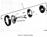
Here you go, military numbers for headlight and BO driving light only, AFAIK.
 

Attachments

mudguppy

New member
1,587
15
0
Location
duncan, sc
attached are many of the discussed modifications / corrections. things not yet addressed:

3) pressure switch in start circuit - what years?
9) CB in flame heater circuit - where, what size?

also, the turn signal indicator ground - following the switching circuit the way the unit is drawn is confusing - i don't see how the bulb should be grounded.

i know that the exact grounding methods are requested, but i need help with that - my deuce does not have all the original grounding points anymore. so if someone would like to spend a few minutes and mark up a drawing with statements like "screw to chassis", "strap to chassis", etc. then i could update.

and, Bjorn, i'm not ignoring the different light switch drawing - it's pretty complicated so it will take me some time to draw it, fit it, and re-draw the connections. that dwg should probably be a seperate version at this point.
 

Attachments

cranetruck

Moderator
Super Moderator
Steel Soldiers Supporter
10,350
75
48
Location
Meadows of Dan, Virginia
Travis, the turn signal bulb is grounded via the hose clamp to the steering wheel column, it is not a failure of the turn signal flasher unit if it doesn't turn on, it may simply not be grounded.

There may or may not be a CB in the flame heater circuit. Wire #55 comes from the accessory switch. Go ahead and leave it out (for comparison, the flame heater on my 757 8x8 has a 15A CB in the circuit).

Some ground connections:
1) Battery (NEG) to frame ( via cable)
2) Engine to frame (via strap)
3) Dash to instrument panel (via 1/4 turn fasteners)
4) Front lamp fixtures to fender (via mounting screws)
5) Headlights to frame (via wire)
6) Fuel in-tank pump and level sending unit to frame (via wire #79 )
7) Engine mounted items to engine (via treads or dedicated wire (flame heater return))
8) Horn to steering column (via horn button)
9) Turn signal pilot light to steering column (via hose clamp)
 

clinto

Moderator, wonderful human being & practicing Deuc
Staff member
Administrator
Super Moderator
Steel Soldiers Supporter
Supporting Vendor
12,596
1,132
113
Location
Athens, Ga.
Can somebody redo this with the circuits in another color other than aqua? Very hard to see and trace.
 

daytonatrbo

Member
320
3
18
Location
Tricities, TN
Not sure if this is allowed, but if anyone is looking for a free CAD tool to make their own edits to this, the DraftSite software from Dassault is quite good and free for personal use. Anyone familiar with the recent updates to AutoCAD will feel right at home.

I'm in no way affiliated with the software, I just happen to use their stuff a lot. They make SolidWorks.
 
Top
AdBlock Detected

We get it, advertisements are annoying!

Sure, ad-blocking software does a great job at blocking ads, but it also blocks useful features of our website like our supporting vendors. Their ads help keep Steel Soldiers going. Please consider disabling your ad blockers for the site. Thanks!

I've Disabled AdBlock
No Thanks