The Schematics!
Sorry for the delay. I also have to admit that what I'm about to share has errors, however if I don't push them out I'll forget.
Attached are PNG versions of the schematics. If you're interested in the Eagle PCB versions PM me.
Here is what each connector/circuit does.
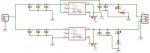
Power:
This board supplies power to the other modules on a shared power bus. The OpAmps I use need a bipolar supply and so this produces +-9VDC for that. The input is wide so that it can be powered from a battery, 12V cars or 24V vehicles. I currently have this connected directly to power in my deuce.
JP1 is the input power, 9-30VDC.
JP2 is the regulated output power, +-9VDC.
The schematic basically hosts 2 DC-DC converters and some filter caps.
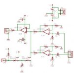
Station:
This is the board that goes at each user station. It interfaces a headset to the intercom audio bus.
JP1 is the audio bus
JP2 is the headphone jack
JP3 is the power
JP4 is the volume pot
JP5 is a jumper to support stereo headphones
JP6 is the mic input.
The OpAmp used is a highend one designed specifically for audio. I use a quad opamp pacakge to get everything I need. The two opamps directly on the audio bus(JP1) are basically buffer amps. The other two are gain amps for the headphones and mic. Finally, because I use a dynamic mic, I inject power to the mic through JP6 but block it using C3
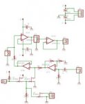
Ipod:
This board lets me inject music onto the audio bus. Since my bus is only a single channel it also mixes stereo down to a single channel.
JP1 is the audio bus
JP2 is the power
JP3 is the audio input( stereo )
JP4 is the PTT signal.
The "a" opamp is the buffer amp, while "b" & "C" are the gain amps for the input. They are fixed gain since most music players have a volume control. They are designed to take normal listening audio from an iPod and amplify it to line level. Its important to note that the audio bus is designed to be line level. Thus the need for gain stages for all input & output connections.
The PTT signal is pulled high normally, and when its shorted to ground its in the "active" state. When PTT is keyed then the MOSFETs short the incoming music signal to ground, effectively muting the music while you talk out a radio. This is also the part where the schematic is wrong. Q2 is a N channel MOSFET which shorts the signal to ground. This works fine until the music signal goes below -0.7V at which point the intrinsic diode withing the MOSFET starts conducting which clamps the signal. The effect of this is really weird sounding music with a bunch of high frequency noise. It sounds like you're overdriving a component in the audio chain, which you kind of are. If your audio stays below +- 0.7V then everything sounds great. The fix for this was to get a solid state, bipolar switch from Analog Devices. This chip is specifically made to switch audio signals and includes zero crossing detection so that it only switches at the zero point. I replaced Q2 with this switch and use that to pull the signal to ground. Now I can have full volume range without any noise. Sadly, I never got around to updating my schematics and I'll have to go back and reverse engineer the thing to update them.
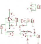
Radio:
This board interfaces a 2 way radio to the audio bus. Its primary job is to implement a PTT circuit, and match audio levels.
JP1 is the audio bus
JP2 is the PTT circuit for the radio.
JP3 is power
JP4 is the TX drive pot
JP5 is the TX signal TO the radio
JP6 is the RX signal FROM the radio
JP7 is the PTT input signal.
The opamps "D" & "A" take audio from the audio bus and push it to the radio. the pot on JP4 is used to set the audio level going to the radio. Typically in my setup this is connected to the radios mic port. As such, I usually have this level set pretty low. As I look at the schematic I just realized an improvement I could make. I should probably insert a block cap right before JP5 incase the radio is biasing the mic line with DC power.
The opamps "C" & "B" take audio from the radio and place it on the audio bus. The important thing to note here is that when PTT is keyed this audio path is muted. This is to stop the radio from creating a feed back loop. On miltary radios specifically when you transmit they play back MIC audio into the handset as a feedback to the operator that the radio is infact transmiting and working. If this feed back path was injected into the intercom again you'd get an unstable feed back loop created. So thats why the RX audio is muted when transmitting. I've never seen this behavior in commercial/ham radios, but since I have military radios I stuck the feature in. It has no effect on other radios. Again Q1 has the same problem as mentioned in the IPod section.
Finally Q3 shorts the radios PTT line to ground to tell the radio to transmit.
General:
As I mentioned in previous posts, my intercom system has 4 channels like military systems. However, all my schamtics only depict a single audio bus( JP1). Outside of this schematic is a rotary selector switch that selects a given intercom channel to feed to each board.
I have individual boards for each function so that my system becomes a distributed system. This then allows me to build/configure what ever I need to. however, all of this could be integrated on to a single board if a centralized system is desired.
Performance:
Once I found the bug on the mute circuits everything works great. I've had this running with several radios and used in my truck all the time and its awsome. The only compliant I have is more a factor of the environment than the intercom. The deuce is REALLY loud and the noise canceling mics on aviation headsets simply can't overcome it on their own. Especially who ever is in the passenger seat. But when the inside of your truck is at 120-130db its pretty hard to cancel that out. Potential ways to solve this in the intercom is to have adaptive filtering on the mic lines, or to not have the mics be hot mics. I've used vehicle intercoms before that you have to explicitly key to talk on the intercom channel and don't really like it. Though, there are certain situations and groups that use things like that. The other option is adaptive filtering which is what the latest military intercoms actually do. I haven't had the pleasure of using those systems yet but I hope I get a chance.
Hopefully this all makes sense, and the guys that wanted the schematics and figure it all out. As always, if you have questions/feedback let me know.