• Steel Soldiers now has a few new forums, read more about it at: New Munitions Forums!

  • Microsoft MSN, Live, Hotmail, Outlook email users may not be receiving emails. We are working to resolve this issue. Please add support@steelsoldiers.com to your trusted contacts.

MEP 002A is ALIVE!

Keith_J

Well-known member
3,657
1,323
113
Location
Schertz TX
Took me less than 2 weeks to get this one running. First issue was the fuel tank, cleaning+welding+POR tank sealer took care of that. Next was the injection pump control lever was frozen. Took it off the IP and cleaned it, same design of pump as a M35's LDT/LDS American Bosch BUT you have to use a mirror to see where the collar is to engage the pawl.

Lots of cosmetic paint/rust issues have been dealt with, the generator head has a fresh coat of POR while the air cleaner is stripped to the galvanized surface. Frame is stripped under the tank since leaking fuel destroyed the finish. So much for chemical agent resistant coating.

The governor was all out of adjustment. Since the frequency meter is inop, I bought a digital multimeter with frequency. Bam, it holds 60 Hz +- 0.25 Hz. Have yet to load test so the current meter function is also questionable. About the only load I can put on it is my welder, will need to double check voltage and frequency before hooking it up to 3 phase (yes, my welder will run on it).

Other issues i ran into was a balky voltage adjustment potentiometer so I tore into that, cleaning it with tuner cleaner/lube. Now it varies uniformly from 0-1000 ohms. The fuel gauge I fixed works great, 5 measured gallons brought it to 3/4 full.

I bought a good bit of clear heatshrink to cover the chipping Nylon jackets on the exposed wiring.

:grd:
 

ETN550

New member
457
9
0
Location
Knoxville, TN
Took me less than 2 weeks to get this one running. First issue was the fuel tank, cleaning+welding+POR tank sealer took care of that. Next was the injection pump control lever was frozen. Took it off the IP and cleaned it, same design of pump as a M35's LDT/LDS American Bosch BUT you have to use a mirror to see where the collar is to engage the pawl.

Lots of cosmetic paint/rust issues have been dealt with, the generator head has a fresh coat of POR while the air cleaner is stripped to the galvanized surface. Frame is stripped under the tank since leaking fuel destroyed the finish. So much for chemical agent resistant coating.

The governor was all out of adjustment. Since the frequency meter is inop, I bought a digital multimeter with frequency. Bam, it holds 60 Hz +- 0.25 Hz. Have yet to load test so the current meter function is also questionable. About the only load I can put on it is my welder, will need to double check voltage and frequency before hooking it up to 3 phase (yes, my welder will run on it).

Other issues i ran into was a balky voltage adjustment potentiometer so I tore into that, cleaning it with tuner cleaner/lube. Now it varies uniformly from 0-1000 ohms. The fuel gauge I fixed works great, 5 measured gallons brought it to 3/4 full.

I bought a good bit of clear heatshrink to cover the chipping Nylon jackets on the exposed wiring.

:grd:
Good job. Post up some pics when you can.
 

Keith_J

Well-known member
3,657
1,323
113
Location
Schertz TX
Carp, I ran it unloaded to get the oil warm (old), then shut down and drained+changed filter. When I went to start it up again, it wouldn't start. The control lever on the IP was stuck DOWN! I jiggled it and it popped up, the engine starting. Guess it isn't perfectly clean.

NAPA had Delvac 1300 Super for $11 a gallon. Perfect oil, the quantity is right and the pop-up spout fits the nozzle perfectly. No funnel needed.

Once warmed again, I tested the voltage output with my true RMS meter (a must here) and was able to adjust from 117 to 141 volts :jumpin: That means it can probably do 230 volts in 3 phase. Which means it will also do at least 8 kW, meaning it will drive my welder up to 200 amps of output. As the duty cycle of the welder is 20% at 200 amps in stick welding mode, that means 2 minutes of welding out of every 10 minutes of clock time. The generator should easily handle that.
Aside from the control lever sticking on starting, I am happy.

Now the low oil pressure switch is inoperative. I'm going to try a hand vacuum pump on the atmosphere port to see if that will clear it. If not:http://www.mixerandplantparts.com/product-p/14242.htm
 
Last edited:

Keith_J

Well-known member
3,657
1,323
113
Location
Schertz TX
Latest repair/refurbishment has been on the wiring. The white wires are coated on the outside with Nylon which has weathered, cracked and flaked off in many areas, mostly the starter/high temperature cut-off and tank switch. Plus the #2 wires to the starter are not coated and the fiberglass has frayed.

I am removing the weathered Nylon and replacing it with clear heat shrink, then covering the groups with black split corrugated loom. I'm also looming the generator's uncoated wires to avoid the fiberglass fraying.

I've depleted the heat shrink inventory at Altex (local electronics supply) in the 1/4" variety, this is needed for #10-12 wire. And will need 5/8" or 3/4" for the #2 starter/slave cable wires.

The ones I have done look good, just less luster than Nylon. Stripping the old Nylon coating isn't fun.
 

Keith_J

Well-known member
3,657
1,323
113
Location
Schertz TX
Partial load test today, two 1250 W space heaters. Frequency with just one is rock stable at 60.5 Hz as adjusted. Put the other one on and still, 60.5 Hz. Voltage is rock stable regardless of load, indicating the regulator is perfect.

When disonnecting the load, frequency jumps to 62.2. Will need a governor adjustment as there is slight hunting, bouncing around 1/2 Hz or so.

I still need to find 3 feet of 1" ID split convoluted loom. This is for the control cubicle main wiring and the 12 generator leads to the reactor/connection switch box.
 

Keith_J

Well-known member
3,657
1,323
113
Location
Schertz TX
The 002A and 003As were designed in 1977 and were replacing 5 and 10 kW gasoline sets as those were retired. New ones were being built until the 1990s. Onan sold a good number of replacement engines, noted by an Onan tag on the blower shroud.

Much has been said about the durability of these engines, as long as they are not abused, they will last forever. The number one abuse is storing without fuel and not running monthly. Even without load, 30 minutes a month will keep the fuel systems in shape. Wet stacking is a myth with these indirect injection engines. As long as the exhaust isn't blue/white when running, they are running far lean with good burn.

I ran a few when I was in the US Army. In one unit, we had both a 5 kW gas and diesel since the prior power generation NCO burned the second gasoline unit in a hot fuel incident. He got chaptered out for an unrelated issue, I was promoted into his position and got the 002A. :D. I ran that as my base load, using the noisy gasoline unit for when changing the oil in the 002A. About two 55 gallon drums between changes. And never used more than 5 gallons of Mogas on a field exercise.

All who think these diesels are noisy have never heard the old gasoline 5kWs. 42 cubic inch opposed twin air cooled beast.
 

Keith_J

Well-known member
3,657
1,323
113
Location
Schertz TX
Partial testing of the frequency transducer showed 80 microamperes at 50 millivolts when running at 60.5 Hz. Just removing the load of 1250 watts (space heater) had the current jump to 110 microamperes for a frequency jump to 61.5 Hz.

I had another issue consuming my time so this is the limit of my testing. I also covered the blower wheel intake to see if the louver movement is working..perfectly. Have not tested the thermal cut-out switch.

Finally ran it at 2.5 kW load resistively to an indicated 60.5 Hz on my digital multimeter. At the same time, I measured the frequency meter current over a 570 ohm resistor at 90 microamperes (uA) at 60.5 Hz and when increased to 65 Hz, it was 180 uA. Dropping down to 55 Hz, current dropped to zero. That is good enough for me.

Now to make a meter that reflects this...not easy. I could take a 0-180 uA direct current meter and make a new scale to make an exact replacement. But I would like to have a digital meter without resorting to a microstamp or PIC programming.

Unless someone has a working spare for less than $50.
 
Last edited:

Keith_J

Well-known member
3,657
1,323
113
Location
Schertz TX
My digital read out meter idea just became a bit closer to reality. I found a cheap way to convert the 0-180 micro ampere transducer output into a millivolt output which matches frequency. Meaning the $9 millivolt meter from Marlin P Jones is perfect.

How you ask? First, the transducer output is loaded with series resistors for total resistance of 580 ohms. This is done with a 64 and ~516 ohm pair. This makes the voltage drop over the 65 ohm resistor to be 5 mV. Using a few 741 operational amplifiers, a stable 55 mV source is then run through a summing op amp circuit to make 60 mV, an analog to 60 Hz. If frequency drops to 55, the current from the transducer drops to 0 meaning the summation op amp now outputs 55 mV. And if the frequency is 65, the transducer is now putting out 170 micro amperes, over the 64 ohm resistor, that is 10 mV. Added to the 55 mV reference, that makes 65 mV! As a benefit, the digital read out can be calibrated over the entire scale.

Total cost? Under $15. I love it when a plan comes together. My Measurements and Instrumentation professor would be proud...wonder if Dr. S. is a member here? Word from the university is he got tired of retired life and went back to professing.
 

steelandcanvas

Well-known member
6,187
85
48
Location
Southwestern Idaho
I am removing the weathered Nylon and replacing it with clear heat shrink, then covering the groups with black split corrugated loom. I'm also looming the generator's uncoated wires to avoid the fiberglass fraying...
Post some photos of your spiral looming material, installed on your genset. I am doing the same thing and would like to compare notes.
 

Keith_J

Well-known member
3,657
1,323
113
Location
Schertz TX
I'm using the corrougated split type conduit. Got a supply of the Nylon stuff, black so it blocks UV, unlike the clear that was on the wiring. Transitions are wrapped with Scotch rubber mastic tape 2228, a thick, self bonding material that stretches and conforms, never getting stiff or losing its adhesive like vinyl. I've used it in exposed connections for 10 years without weathering.

Install the conduit with the split down to drain properly. You have to use larger cable clamps, these I found at the local auto parts store.

I still need to take the air filter assembly off to top coat the generator as I was anxious to get it up and running. And now with all my digital read out frequency meter work, I have no time. Still haven't found my camera. And still haven't run a maximum load test. Should have a few 4500 watt water heater elements for a good load. Going to install them in PVC pipe and run water through them as my safer load bank. At 5 GPM, even 10 kW loads won't get but about 15 degrees warmer.
 

Keith_J

Well-known member
3,657
1,323
113
Location
Schertz TX
Finally a useful load today. I was gifted a 1980s era Jepson 14" abrasive cut-off saw and used the generator in 120 V two-wire config, just a pigtail drop off the load terminals with NEMA 5-20 duplex receptacle. The saw is rated at 14 amperes but that doesn't count reactive power. The ammeter on the 002A measures reactive plus real power. So, onto the real load.

Starting the saw, the current jumps to 50% for just a moment. This is inrush current which is partly reactive plus inertia of swinging that 14" abrasive blade. When grinding in a 1-1/2" cut, the ammeter could be held at 75% with firm pressure on the handle. That is 40 amperes which would cause issues with the plug, receptacle and wiring. But nothing happened.

Frequency didn't budge more than 1/2 Hz. No smoke, either from the electrical or diesel side. My digital frequency meter didn't like it AT ALL, it dropped to 4-5 Hz, showing the effects of the low power factor.

My other digital volt meter was reading the voltage off a 780 ohm resistor connected to the output of the frequency transducer. It read analog frequency with great stability, the shunt "converted" the transducer's current into analog frequency where 60 mV equals 60 Hz. Sometimes, analog meters are better. Hopefully my digital read out meter conversion will work, I'm still hashing out the prototype and running into power issues, will have to run a 24 volt line from the battery meter.
 

Keith_J

Well-known member
3,657
1,323
113
Location
Schertz TX
So far, I've put 10 hours on it. About 6 of those it was powering my welder, about 6 amperes in 3-phase average draw.

The tank and filters were bone dry, I have put 10 gallons in it meaning it has only burned 3.25 gallons. Yes, it burns a lot more than 1/3rd gallon an hour when the welder is running. Of course I cannot see the ammeter when welding, I'm just using the welder's specifications.

Once this current project is done, I'm going to make a bundle of four 3/32" E6013 electrodes and turn the machine up to 200 amperes. That is a 7.8 kW load
 

n1oty

Member
Steel Soldiers Supporter
170
1
16
Location
Taunton, MA
I'm hoping to do a serious load test of my new generator sometime over the next couple of weekends. I'll be interested to hear your findings regarding max load and fuel economy.

John
 

ETN550

New member
457
9
0
Location
Knoxville, TN
Partial testing of the frequency transducer showed 80 microamperes at 50 millivolts when running at 60.5 Hz. Just removing the load of 1250 watts (space heater) had the current jump to 110 microamperes for a frequency jump to 61.5 Hz.

I had another issue consuming my time so this is the limit of my testing. I also covered the blower wheel intake to see if the louver movement is working..perfectly. Have not tested the thermal cut-out switch.

Finally ran it at 2.5 kW load resistively to an indicated 60.5 Hz on my digital multimeter. At the same time, I measured the frequency meter current over a 570 ohm resistor at 90 microamperes (uA) at 60.5 Hz and when increased to 65 Hz, it was 180 uA. Dropping down to 55 Hz, current dropped to zero. That is good enough for me.

Now to make a meter that reflects this...not easy. I could take a 0-180 uA direct current meter and make a new scale to make an exact replacement. But I would like to have a digital meter without resorting to a microstamp or PIC programming.

Unless someone has a working spare for less than $50.
Not sure how similar the transducers are between your 002 and my 016B but the cal screw in the transducer box will drop the needle from 65 to 60 with about half the range of turn limits of the screw. In other words this might help you match a meter to it a little easier. The system on the 016b is supposed to be 0 uA at 55 and 200 uA at 65 and linear but 55 is not the bottom of the meter movement and I think some uA is needed to display 55.

Housing on the 016b transducer reads:

Frequency Transducer
Precision Electronics, Inc.
Copiague, NY
120VAC 55 65 1100 ohm symbol
P/N 4431.1
 
Last edited:

Keith_J

Well-known member
3,657
1,323
113
Location
Schertz TX
Little change on the frequency meter replacement. I have been using my digital volt meter in the 200 micro-ampere setting, hooked up to the transducer to read frequency as 60 Hz corresponds to 100 micro-amperes.

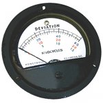
Well, I managed to find a 0-200 micro-ampere meter in a 3-1/2" case just like the original. Only thing I have to do is open the new one and swap out the scale. Yes, sealed but that didn't keep me from opening both the current and frequency meters and repairing the current (I) meter. Price? $19.

Arbitrary Meters - < 1 ma


The replacement is a "Deviation in kHz meter", probably off radar equipment but with a 200 micro-ampere full scale (that is what "fs" is), the movement is identical.

This way I won't have to build a correction circuit (voltage summing op amp) to use a millivolt meter in lieu of the arbitrary scale 0-200 micro-ampere meter.
 

Attachments

n1oty

Member
Steel Soldiers Supporter
170
1
16
Location
Taunton, MA
Little change on the frequency meter replacement. I have been using my digital volt meter in the 200 micro-ampere setting, hooked up to the transducer to read frequency as 60 Hz corresponds to 100 micro-amperes.

Well, I managed to find a 0-200 micro-ampere meter in a 3-1/2" case just like the original. Only thing I have to do is open the new one and swap out the scale. Yes, sealed but that didn't keep me from opening both the current and frequency meters and repairing the current (I) meter. Price? $19.

Arbitrary Meters - < 1 ma


The replacement is a "Deviation in kHz meter", probably off radar equipment but with a 200 micro-ampere full scale (that is what "fs" is), the movement is identical.

This way I won't have to build a correction circuit (voltage summing op amp) to use a millivolt meter in lieu of the arbitrary scale 0-200 micro-ampere meter.

If swapping the scale is a simple process, go for it. If not, I'd simply install the new meter and put a red nail polish/paint mark at the 60 hertz mark and call it a day!! I've never opened one of these panel meters before. Is it a simple process?? Or is it problematic due to the sealing process??

John
 

Keith_J

Well-known member
3,657
1,323
113
Location
Schertz TX
The hardest part of opening these meters is the threaded ring, about 3/16" thick and deep and 2-3/4" in diameter. It is made of pot metal with 4 notches for a wrench. Which I don't have. So I use a punch which breaks the locking ring as it was never intended to be removed.

Once the meter is working, take locking ring fragments and some RTV silicone sealant to piece it back together.

The generator just passed a brief 7.8 kW test. I used my welder in stick mode (SMAW) with 4 parallel electrodes (3/32" E6013) since I didn't have a 3/16" electrode handy, nor any 1/4" thick steel. Frequency dropped to 58 Hz, voltage output (208) didn't drop a bit. No smoke, hunting or complaints, just a beautiful engine sound.
 
Last edited:

Keith_J

Well-known member
3,657
1,323
113
Location
Schertz TX
The generator's little issues have all been fixed. The rotted frequency meter was replaced with a new movement, just swapped the dial as the $19 one I found was for a totally different application but had the same electrical-mechanical characteristics. And the low pressure switch was sourced from a commercial vehicle parts supplier.

So what have I been doing with it? Powering my backyard welding works. Actually, too cold/windy for welding but have been using it to power the abrasive cut-off saw, building the ultimate accessory for a MEP-002A. That is powered wheels to move it over soft ground. No, you cannot drive it but you won't have to pull it either.

I found a 24 volt DC motor which is rated at 1/2 HP and 24 foot-pounds of torque at 110 RPM. It is driving a 2-speed riding lawn mower transaxle, with reverse and open differentials. For steering, I welded a simple tie rod arrangement with a pivoting T-bar handle. I tried moving it over the lawn and it was still too much, hence the power.

Still have a few parts coming in to complete it so I ran the calculations for rear wheel torque...far overkill. The gearing was for safe speed of 1 MPH, this provides rear wheel torque of 1600 foot-pounds. Translating into 2800 pounds of drawbar pull IN TOP GEAR!!. That could pull it up a 45 degree slope.

Still have to cut some steel tube to mount the transaxle to the generator's frame. And don't have a suitable speed controller so it will be fed 12 volts to prevent wheelstands (center of gravity is about 12 inches in front of the driven axle, unit weighs 1050 pounds so with 1600 foot-pounds of torque, it WILL)
 
Top
AdBlock Detected

We get it, advertisements are annoying!

Sure, ad-blocking software does a great job at blocking ads, but it also blocks useful features of our website like our supporting vendors. Their ads help keep Steel Soldiers going. Please consider disabling your ad blockers for the site. Thanks!

I've Disabled AdBlock
No Thanks