
Hello!
@HDN - thanks a lot for your comment! I think you're right. After you pointed it out I even found the right part in the kit.
Took a little longer than I thought, but I've got another update - I was working on the chassis and also on the cab:


As you can see I’ve replaced the bumperettes with sheet metal to hopefully make them look better.
Similarily I’ve had an accident with the step boxes and I repaired them with other sheet metal:

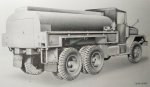
I also started working on the tank. First I had to cut off the later sides:

Then I had to do some fixes and tweaks:

I'll soon have everything ready for the 3D printed older sides.
I was also working on custom decals and now I'm waiting for them to print.
That'd be it for now - thanks for looking and have a nice day
Paweł
@HDN - thanks a lot for your comment! I think you're right. After you pointed it out I even found the right part in the kit.
Took a little longer than I thought, but I've got another update - I was working on the chassis and also on the cab:
As you can see I’ve replaced the bumperettes with sheet metal to hopefully make them look better.
Similarily I’ve had an accident with the step boxes and I repaired them with other sheet metal:
I also started working on the tank. First I had to cut off the later sides:
Then I had to do some fixes and tweaks:
I'll soon have everything ready for the 3D printed older sides.
I was also working on custom decals and now I'm waiting for them to print.
That'd be it for now - thanks for looking and have a nice day
Paweł


 At least that's how they were on my dad's M37 before he switched to the newer large-lens markers.
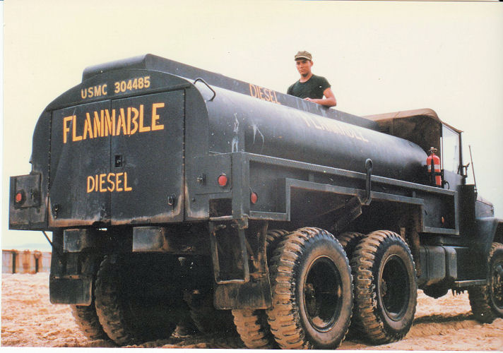
 Kinda like the one picture of a fuel truck you posted where it appears the tail lights were removed.