• Steel Soldiers now has a few new forums, read more about it at: New Munitions Forums!

  • Microsoft MSN, Live, Hotmail, Outlook email users may not be receiving emails. We are working to resolve this issue. Please add support@steelsoldiers.com to your trusted contacts.

1083 A0 Fuel Solenoid issue (3116)

Shiflett

Member
Steel Soldiers Supporter
28
28
18
Location
32789, Florida
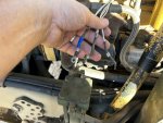
Reposted here from 5 ton section…Legends, thanks in advance for your help. I’ve tried to consult the TM’s but have come up short. The PO had the fuel solenoid hard wired directly to the batteries through a mechanical switch in the battery box. This meant to stop the engine you had to hop out. I’m working to rerun the wiring to the original setup.

Facts:
1. Fuel solenoid hack worked. Ground to the solenoids top post, 24v to the bottom post. Engine started and ran perfect.
2. Batteries are charged
3. CB79 has 24v and new fuse
4. K1, K19, K24 all have new relays and 24v
5. Start inhibitor has failed but is now bypassed and has 24v
6. TL 28 (wires 54-p31 and 1441-p31x) was disconnected and has 10v
7. TL29 (wires 3015-p31 and “p33 1”) and TL66 (wire 3027-p201) were connected to the bottom of the solenoid, with the hack mentioned above.

Seems like TL28 is grounding somewhere to have that much voltage drop…if it’s supposed to have 24v

Questions:
1. Can someone point me to the correct TM and section.
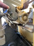
2. Would someone take a picture of their 3116 fuel solenoid for reference
3. Could some verify which wires go to what post.
4. Is it possible the solenoid had its own ground wire making it a total of four wire connections?

I appreciate any help.IMG_0037.jpegIMG_0038.jpeg
 

Ronmar

Well-known member
3,881
7,549
113
Location
Port angeles wa
Ok, TL66 should not even be in the mix. It says not used in the A0 schematic, and the other pin on P201 runs to the idiot light panel, but is not shown being attached to any idiot light. If it was intended to drive a light, TL66 may have been intended to be connected to ground(TL29) to complete a lighting circuit.

TL28 is your 24v input, wire 54 from K19-87A via P31-14. The other wire 1441 that goes to P31X is not used. It is for the standardized test equip and runs to the big cannon plug in front of your left knee when in the drivers seat. You can disconnect and tape it off to eliminate it as a possible issue.

TL29 is your ground, wire 3015 back thru P31-5 to TB2(ground terminal block under power dist panel). The other wire 3017 goes to the heater on the bowl of the water separator and provides the ground for that heating element.

So you say the start inhibit is “bypassed” how is it bypassed? K19 provides that solenoid power down wire 54, so it needs 24V on pin 30 in the relay socket and that 24V needs to be jumped over to pin 87A to feed power down to the solenoid. one of the places in the panel that must have a 5 pin relay installed.

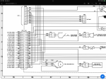
Here is a snap of the solenoid wiring in the A0 schematic.

you can find the 1078 A0 service manuals up in the manuals section on the home page, under present conflict vehicles. There is a schematic in the back of each of the manuals…

IMG_3785.png
 

Shiflett

Member
Steel Soldiers Supporter
28
28
18
Location
32789, Florida
Ok, TL66 should not even be in the mix. It says not used in the A0 schematic, and the other pin on P201 runs to the idiot light panel, but is not shown being attached to any idiot light. If it was intended to drive a light, TL66 may have been intended to be connected to ground(TL29) to complete a lighting circuit.

TL28 is your 24v input, wire 54 from K19-87A via P31-14. The other wire 1441 that goes to P31X is not used. It is for the standardized test equip and runs to the big cannon plug in front of your left knee when in the drivers seat. You can disconnect and tape it off to eliminate it as a possible issue.

TL29 is your ground, wire 3015 back thru P31-5 to TB2(ground terminal block under power dist panel). The other wire 3017 goes to the heater on the bowl of the water separator and provides the ground for that heating element.

So you say the start inhibit is “bypassed” how is it bypassed? K19 provides that solenoid power down wire 54, so it needs 24V on pin 30 in the relay socket and that 24V needs to be jumped over to pin 87A to feed power down to the solenoid. one of the places in the panel that must have a 5 pin relay installed.

Here is a snap of the solenoid wiring in the A0 schematic.

you can find the 1078 A0 service manuals up in the manuals section on the home page, under present conflict vehicles. There is a schematic in the back of each of the manuals…

View attachment 909896
Thank you so much. This is very helpful. Your response is incredibly through.

1. Inhibitor has a temporary jumper wire between the two leads. 24v was coming in. I need to verify 24v is coming out.
2.TL 28 on the top and TL29 on the bottom…if it’s getting 24v will work.
3. If I can’t get TL28 to make 24v, then I could run a new wire from the inhibitor to the top post of the fuel solenoid.
4. I’ll go download the manuals. I had been piecing them together from other internet sites.
 

Shiflett

Member
Steel Soldiers Supporter
28
28
18
Location
32789, Florida
TL 28 is still at 10v despite removing 1441. I’m going to start tracing it back to find the short. Wherever it has shorted is not enough to blow the fuse.

if I can’t locate the short I’ll run a new line.

Thanks again for your help.
 

Ronmar

Well-known member
3,881
7,549
113
Location
Port angeles wa
TL 28 is still at 10v despite removing 1441. I’m going to start tracing it back to find the short. Wherever it has shorted is not enough to blow the fuse.

if I can’t locate the short I’ll run a new line.

Thanks again for your help.
Is that 10V when it is connected to the run solenoid, or with TL28 disconnected?
 

Ronmar

Well-known member
3,881
7,549
113
Location
Port angeles wa
Voltage is not considered good until it is tested under load. Resistance resists current flow NOT voltage. A bad/high resistance connection, like a kink in a garden hose, will still pass full voltage/pressure to the end of the wire/hose until you try and pull current thru it/flow water. Then the voltage/pressure will fall off due to resistance/restriction.

i was hoping you were going to say that 10V was when connected. It being 10V when disconnected/unloaded is confusing. Even a really crappy connection should still be able to show the 24v applied at K19 and the load of the run solenoid coil would knock it down.
Are you sure how 24V is jumpered at K19? It comes in on pin 30 from TB1 pin59. That power originates at CB79 which also powers your transmission.

if you have 24V at K19-30, it only needs to be jumpered to pin 87A in the K19 relay socket. Which is what happens when you plug in a 5 pin relay. De-energized, a 5 pin relay provides a circuit from 30-87A. When you push the start inhibit button K19 energizes and breaks that 24v connection between 30-87A and removes the run solenoid power. So whats keeping you from plugging in a 5 pin relay into the K19 socket?

If you have good 24V to pin 87A at the K19 socket, what is causing the drop to 10. That would have to be a bad connection PLUS a short to both provide high resistance and a load to drop the voltage at TL28…
 

Shiflett

Member
Steel Soldiers Supporter
28
28
18
Location
32789, Florida
1. I replaced all the fuses (bussman) and relays (bosch) last night and should recheck voltage.
2. I had incorrectly assumed the start inhibitor switch was between K19 and TL28 (wire 54)
3. Start inhibitor has 24V with a temporarily solid copper wire (12 gauge) jumper
4. CB79 fuse is good and has 24v
5. I'll reverify pin 30 has 24v

The old relay could have caused the voltage drop, i had assumed k19-87a had 24v because the start inhibitor did. I'll recheck voltage at TL28 now I have the new relay in.
 

Ronmar

Well-known member
3,881
7,549
113
Location
Port angeles wa
1. I replaced all the fuses (bussman) and relays (bosch) last night and should recheck voltage.
2. I had incorrectly assumed the start inhibitor switch was between K19 and TL28 (wire 54)
3. Start inhibitor has 24V with a temporarily solid copper wire (12 gauge) jumper
4. CB79 fuse is good and has 24v
5. I'll reverify pin 30 has 24v

The old relay could have caused the voltage drop, i had assumed k19-87a had 24v because the start inhibitor did. I'll recheck voltage at TL28 now I have the new relay in.
The start inhibit switch powers the coil of K19. When K19 energizes, it disconnects power to wire 54 down to the run solenoid and applies it to its own coil to latch in the on/start inhibit position untill you shut off the ign switch.

when you shutoff ign, This resets relay K19 to the off/deenergized position and again allows it to power the run solenoid via 87A/wire 54 when the ignition sw is again powered on...
 

Shiflett

Member
Steel Soldiers Supporter
28
28
18
Location
32789, Florida
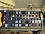
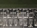
K19 pin 30 and 86 have 24v. Now TL28 has 0 volts since I replaced all the fuses and relays…and raised/lowered the cab twice. I did ring out all the fuses. I can hear k19 energize. Per your knowledge, is there anything else between k19 and TL28?
IMG_0052.jpeg
 

Ronmar

Well-known member
3,881
7,549
113
Location
Port angeles wa
Ok, you have 24V on pin 86 With ignition on? That should only happen when the start inhibit button is pressed… if it is hot all the time, it would energize K19 as soon as ign is turned on, and disconnect power to the run solenoid/TL28… And of course K19 is a 5 pin relay right?
 

Shiflett

Member
Steel Soldiers Supporter
28
28
18
Location
32789, Florida
Good morning and thank you for all your help, feels like you are going way above and beyond. I do appreciate it. I have found the “engine won’t start” section in TM “…366-20-1” and have started walking through the steps.

1. All tests are with ign. on
2. Inhibitor switch was connected. It is not anymore.
3. K19 (5 pin solenoid) has 24v only on pin 30 when checked with the relay removed.
4. K24 (if it matters) has 24v on pins 30 and 86 with the relay removed.
5. I don’t get 24v on K19 pin 87…with the solenoid in, which I assume is the same as 87b…correct? So the relay is not transferring power from pin 30 to pin 87. I tried multiple relays, I need to find out what is stopping it from switching over.

so does K19 pin 86, determine if 87a to 87 gets power from pin 30?If so I need to trace what triggers 86.
 
Last edited:

Ronmar

Well-known member
3,881
7,549
113
Location
Port angeles wa
5. I don’t get 24v on K19 pin 87…with the solenoid in, which I assume is the same as 87b…correct? So the relay is not transferring power from pin 30 to pin 87. I tried multiple relays, I need to find out what is stopping it from switching over.

so does K19 pin 86, determine if 87a to 87 gets power from pin 30?If so I need to trace what triggers 86.
there is no 87B, only 87 and 87A. When de-energized, pin 30 connects to pin 87A. When the relay coil is powered the internal contacts switch, opening the contact between 30-87A and closing the connection between 30 and 87. Pin 85 and 86 are the coil connections. In the case of this truck, pin 85 will always be connected to ground, and pin 86 gets voltage applied. When you apply voltage to a coil itand current flows thru it to ground, a magnetic field is created pulling the pin 30 contact bar from 87A to 87.

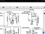
here is the drawing showing K19. In this case the monkey with the crayon did not draw it very well. The relay to the left is a 4 pin and shows it better. Pin 30 at the top connects to the angled line just above the point labeled 87. If that relay had a 87A that angled line would be touching it(De-energized).

the curved line drawn on K19 in this pic is supposed to connect pin 86 to pin 87. This makes a latch. When you apply power to 86, the relay energizes and connects the power from pin 30 to 87. This power now flows back to power the coil so the relay cannot shutoff untill all the power is removed(ign sw off).

there is no need for K19 to operate, unless you are pushing the start inhibit switch to energize it, in this case it can be replaced by a jumper wire with a 1/4” male spade connector crimped to each end. The relays have 1/4” tabs that plug down intot he socket. EVERY person who has one of these trucks should have some of these jumpers, to bypass a bad relay or a problem circuit…

IMG_3786.png
 

Ronmar

Well-known member
3,881
7,549
113
Location
Port angeles wa
In the case of K19, you would jumper the 24V from the top center pin 30 to the pin directly below it, 87A(Shown in yellow below). With a jumper you can measure that 24v is actually being applied to pin 87A in the K19 socket. Using a jumper also checks wether the modular panel connections(female crimp-on spade connectors held in place with a plastic wedge) are also OK. A broken or missing wedge would allow the socket connection to pull out the bottom of the panel breaking the connection to the relay…

from the back side of the power panel, K19 87A runs with the wire bundle down thru the dash, out of the cab and down to the engine to P31-14.

I have never actually located P31, but because all the engine wiring runs over to the drivers sice, I suspect it is located tucked into the drivers frame rail, wrapped up in the cable bundle between radiator and air compressor… P31 pin 14 should continue on to TL28 via wire 54…

IMG_3787.jpeg
 

Shiflett

Member
Steel Soldiers Supporter
28
28
18
Location
32789, Florida
Thanks for your patience.


"there is no 87B, only 87 and 87A." thanks for the clarification, the wire schematic from Sunday looks like wire 54 is connected to K19 87B.

The back side of K19 looked good this morning, and I did a quick trace of the wires and didn't see anything that stood out as kinked or crimped.

I'm going to do a continuity test from the fuel solenoid to K19 pin 87a. If its bad, I'll run another wire.
 

Shiflett

Member
Steel Soldiers Supporter
28
28
18
Location
32789, Florida
Issue SOLVED!!! Thank you Ronmar!!!

K19-87a was loose and very weak ground at the solenoid. I fixed the connector and ran a ground to the battery box.

I cannot thank you enough for taking the time to problem solve this issue. I hope I get the chance to repay your kindness and patience to the next person who needs help.
 
Top
AdBlock Detected

We get it, advertisements are annoying!

Sure, ad-blocking software does a great job at blocking ads, but it also blocks useful features of our website like our supporting vendors. Their ads help keep Steel Soldiers going. Please consider disabling your ad blockers for the site. Thanks!

I've Disabled AdBlock
No Thanks