• Steel Soldiers now has a few new forums, read more about it at: New Munitions Forums!

  • Microsoft MSN, Live, Hotmail, Outlook email users may not be receiving emails. We are working to resolve this issue. Please add support@steelsoldiers.com to your trusted contacts.

#2 MEP 805B oh the joys

155mm

Chief and Indian
Steel Soldiers Supporter
1,183
407
83
Location
Guymon, OK
yet another delay of game, trying to warm it up to flush the cooling system, and the dang thang shut down, said it was out of fuel, i guess when everything started to work right, then it said, 'oh my gauge says i am out of fuel' Luckily I bought/ordered 2 senders when #1 sender took a dump. Will be backup and running after a quick bite to eat. I guess i should be writing these part numbers down to share with the others that might need them.
 
Last edited:

baxter462

Member
79
2
8
Location
Salt Lake City Utah
You can electrically disconnect the fuel level sensor as a work around. It'll set an sensor fault code, but you can clear it with the fault reset switch and continue running that engine. I think you might be able to use the battle short switch to keep it running also, although it might be tricky to get it to start in the first place.

By the way, those fuel level sensors are easy to take apart and clean up to get them working again. A little bit of really fine sandpaper and slightly stretching out the spring between the contacts works wonders on them. Just be careful not to lose the little contacts on both sides of the spring.
 

155mm

Chief and Indian
Steel Soldiers Supporter
1,183
407
83
Location
Guymon, OK
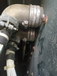
Well these loose cannon plugs sure might have alot to do with alot of #2's issues. Both p5 and p6 are floppy loose. Best guess they are cross threaded.

simage.jpg
 

155mm

Chief and Indian
Steel Soldiers Supporter
1,183
407
83
Location
Guymon, OK
Ok iam at a loss, i have continuity from the oil psi plug to the convience plug with the master on, engine off. Does the oil psi sending unit operate on 120v?
 

baxter462

Member
79
2
8
Location
Salt Lake City Utah
No, it doesn't. That's probably a misleading result. Continuity/resistance measurements are only valid on isolated (not powered up) circuits. With the master switch on, circuits are live and you're likely getting invalid readings.
 

155mm

Chief and Indian
Steel Soldiers Supporter
1,183
407
83
Location
Guymon, OK
That'll do it. It really makes me think someone was swapping a bunch of parts between generators trying to fix something.
Yeah after working on it all day, i have to agree that someone was swapping parts. I think this one is going to be more electric trobleshooting than the first one
 

PJL

Member
140
6
18
Location
Way south of Seattle, WA
I have a junk MEP-806B with a dark screen CIM. If you need parts from it let me know. The whole thing is going to the junk heap otherwise. I have a pair of low time 805-B's that needed a few parts that I swiped from the 806.
 

155mm

Chief and Indian
Steel Soldiers Supporter
1,183
407
83
Location
Guymon, OK
Just finished with a contolled exchange, the oil pressure sw is what the problem was. I installed the bad one from #2 on #1 and it showed -24 psi.... well that was an ez fix. Now to find the oil pressure switch. 6620-01-470-3854
 

Guyfang

Moderator
Staff member
Moderator
17,038
24,913
113
Location
Burgkunstadt, Germany
Switch Manufactures name:

MEASUREMENT SPECIALTIES INC1000 LUCAS WAYHAMPTONVA23666-1573UNITED STATES

Phone number and FAX
757-766-1500757-766-4297


Original cost: $126.00

The switch should be the same as PJL's MEP-806B Work something out. Mabe for more then just the switch?

Do not assume the canon plugs are crossthreaded. Often, when someone swapped out the Backplane, they cheated. The quick and dirty way to change it is to do it without removing the control cubical. Yeah, its a super PITA, times ten. But its possible to do it without removal. The two cannon plugs are a REAL PITA to get off and on, when the control cube stays bolted in. A good mechanic will stay at it until it's finished right. A bad one will leave you with what you got. Loose plugs. Remove them, spray some WD/40 on both sides of the plugs, that makes it 10,000,000,000 times easier. Small hands and forearms are a definite plus when doing this. Be warned. Removal of the control cube can lead to temporary insanity. Normally you will break off about 50% of the screws you try to remove. Having a LOT of extras on hand, is a good idea.
 
Last edited:

Guyfang

Moderator
Staff member
Moderator
17,038
24,913
113
Location
Burgkunstadt, Germany
No, it doesn't. That's probably a misleading result. Continuity/resistance measurements are only valid on isolated (not powered up) circuits. With the master switch on, circuits are live and you're likely getting invalid readings.
He who believes an Ohms reading, does so at his own risk. As Baxter says, "Continuity/resistance measurements are only valid on isolated (not powered up) circuits.

Also, often, ohms tests shows continuity, but fail in real life, because a broken wire WILL pass volts, but NOT amps. And you can get continuity when a wire is broken. Its best to always isolate anything you do an ohms test on.
 

Guyfang

Moderator
Staff member
Moderator
17,038
24,913
113
Location
Burgkunstadt, Germany
You can electrically disconnect the fuel level sensor as a work around. It'll set an sensor fault code, but you can clear it with the fault reset switch and continue running that engine. I think you might be able to use the battle short switch to keep it running also, although it might be tricky to get it to start in the first place.
By the way, those fuel level sensors are easy to take apart and clean up to get them working again. A little bit of really fine sandpaper and slightly stretching out the spring between the contacts works wonders on them. Just be careful not to lose the little contacts on both sides of the spring.
Durring start up, most of your protective circuits are bypassed. So starting should not be a problem. But when you want to use the S-7, (Battle Short), do so before releasing the S-1. Then it will continue to run.
 

Guyfang

Moderator
Staff member
Moderator
17,038
24,913
113
Location
Burgkunstadt, Germany
Roger that! If you ever get a chance to acquire a version 3, I would do it. Kinda hard to find, and rarely cheap. But not a bad investment. Version 1 and 2 are prone to fail due to dust and dirt getting into the switch. Makes it hard to turn, and then the shaft breaks, or contacts inside the switch don't make or break. ALL TQG's use the same S-1 switch. Hint, Hint.
 

Guyfang

Moderator
Staff member
Moderator
17,038
24,913
113
Location
Burgkunstadt, Germany
I have a junk MEP-806B with a dark screen CIM. If you need parts from it let me know. The whole thing is going to the junk heap otherwise. I have a pair of low time 805-B's that needed a few parts that I swiped from the 806.
PJL,

Go to the TM section of SS. Find the file for the 30 or 60 KW B-Modal gen sets. There is a file there titled CIM Checking Procedure. Read it all. The last few paragraphs tell you how you MIGHT be able to undarken your dark CIM. No promise, but this procedure has saved a bunch of CIM's over the years. Thats money in your pocket!
 

155mm

Chief and Indian
Steel Soldiers Supporter
1,183
407
83
Location
Guymon, OK
I removed the cubical so that i could clean up the threads on the cannon plugs. I see where it would be a pita, there is a support structure right in the way when trying to remove those cannon plugs. I didnt have any issues with the bolts coming loose, it appeared that the unit had either been painted since the cubic was installed or it has not been remove before, it does say CARC 04. They may have swapped the backplane out without removing the cubical.

I did find another company that had the senders for $70
http://www.mouser.com/ProductDetail...00-100-P-3-N-1/?qs=Pz4gaf3%2b8zxTYNsaorwRog==
I didnt like the one on fleabay, it was only a 3 wire and he wanted 100 bucks for it.

I think that todays project will be to get the cooling system flushed/pressure tested and then see if we can figure out why gen voltage says 0 on all 3 legs when the engine is running.

Talking to PJL about parts, since he posted he has a donor, i guess his inbox exploded with requests.
 

Guyfang

Moderator
Staff member
Moderator
17,038
24,913
113
Location
Burgkunstadt, Germany
Check your AC voltage at the TB-1 Voltage reconnection board. You can follow it from the Main gen output, to the CB-1, then through the CB-1 when you close it, and on down to the output lugs. Don't forget, that if the CT-1 is not hooked up, or doesn't work, you screen will read 0 volts. You could get a big surprise if you placed your hand on TB-1, if that were the case. Never assume!

The no AC output in the troubleshooting if not to bad a lead, to correcting this problem.
 

baxter462

Member
79
2
8
Location
Salt Lake City Utah
As a quick note on the issue no generator voltage output, make sure you're following the actual startup sequence (specifically, turning the engine switch to the crank position for a couple seconds after the engine is running). I suspect they used two different designs of voltage regulators in these. One of my 805b units produces power immediately after starting it, and the other won't until I excite the field by turning the switch to crank a second time. Most of the videos I've seen on YouTube show that extra step before the generator will produce power, but a few appear not to need it. Like I said, I suspect there are two different revisions of the voltage regulator, and they behave differently when it comes to initially exciting the field.
 

Guyfang

Moderator
Staff member
Moderator
17,038
24,913
113
Location
Burgkunstadt, Germany
Heres another stupid reason some people could not get the AC voltage to work. The volt regulator is 60 hertz. That means you need a volt regulator with a UOC of LTV. Often, components in the control cube were found to be 400 hertz components, UOC of LTW. It never hurts to compare the part numbers on the components, to the part numbers in the book. Most parts are compatible between the MEP-806B and MEP-816B, but not all. The Backplane, Voltage Regulator, Electric synchronizer and the Main Generator are the four big ones that often get mixed up. There are a few other parts, but not many.
 

155mm

Chief and Indian
Steel Soldiers Supporter
1,183
407
83
Location
Guymon, OK
I did check volts at a tb1, had 25 volts on the 6 bortom posts, was looking in the case and the covers were loose on the backplane, so i took the covers off, all of the circuit boards were missing the mounting skrews and had alot of dust in the so, next isfind nuts and get it cleaned up and put back together. After its back together, i will try the starter bump technique to maybe flash the field
 
Last edited:
Top
AdBlock Detected

We get it, advertisements are annoying!

Sure, ad-blocking software does a great job at blocking ads, but it also blocks useful features of our website like our supporting vendors. Their ads help keep Steel Soldiers going. Please consider disabling your ad blockers for the site. Thanks!

I've Disabled AdBlock
No Thanks