J...how does the diamond shape help distribute the load sandwich, its reduced shape reduces surface area on the clamping area? Does a large radiused edge create less stress within said plate by not having sharp points to crack? I would radius more but I didn't want to invite more water and debris into this joint area to cause frame rot. ...Refering to the big plate little plate sandwich rig, what determines which side gets the larger plate? I would guess in the pic. shown that the bottom would be larger pushing up on the frame and the top could be smaller used as a washer type unit for the nuts to grap and dis-suade any warpage to the existing part (frame bottom side).
Exactly. We're talking about radiuseses in two direction here. 1st is the shape of the plate if you were looking at it from the top/bottom, and 2nd is the front/back edges/corners of the brackets where the brackets contact the frame the framerails. The idea is to reduce the stress that's concentrated on any one area, so you want to avoid the sharp edges and straight lines across your framerails.
As far as the shape of sandwich plates, if you think about it for a second, it should be obvious how/why that will create exactly the type of stress concentrations that you should be trying to avoid. You would want to make the top plate larger if you were mounting something like a rollcage to the floor of a Jeep tub (because you don't want the rollcage punching through the floor if/when it rolls), but in this application it's more about the pushing/pulling/twisting forces. All I'd do is create two plates with a similar amount of total surface area, but with different shapes on the front/back edges. Does that make sense?
Do you disaprove of this mouting location because of the chance of destroying this section of frame? What I was thinking is that this mounting point would receive push/pull pressure, but at an angle equal to the angle of the bars attached here. I now think I see what you mean, this 2-1/4" area is going to get flexing pressure causing it to try to flex up and down and fatigue.
I got a peek at those hot looking brackets that look like spring perches in your CAD pic. a while back. I was going to ask you about that design and possibly using it here if you approve. Which CAD program do you have that in if you may still have it?
Yeah I would just prefer to tie into stronger parts of the frame. That's why I designed those mounting brackets to bolt to the framerails right under that crossmember behind the rear axle. Much stronger than if they were bolted to an unsupported part of the framerails, and this also eliminates the need to use backing plates on the bottom edges (would still use large hardened fender-washers on the sides).
Started another thread with links to
CAD files that I uploaded to the CAD Library. Free for everybody to download and use, modify, whatever. I use
SolidWorks, but also uploaded and IGS file (universal file format that most CAD programs can open) and an eDrawings file (for all everybody that doesn't use CAD).
eDrawings is a free CAD viewing program that anybody can download and use to open CAD files like these. Very cool.
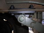
The only problem is that the pic. shows what I now have and to determine the precise length pin hole to pin hole I would need to grind out my rivets and install one on my truck to get all this right. Any suggestions? Like I said I didn't want to drill out mine just to measure this up. Looks like some fancy math.
Not sure what's so tricky about that? No fancy math, just took some measurements and made a best guess. Won't know for sure if my measurements are spot-on until somebody actually makes parts and tries to install them. That's just the nature of this kind of design work.
Would you also recomend heavy wall 1"x2" box tubing instead of solid? I reeeeeealy want to stick to this 1x2 dimention.
Sorry, I'm not an engineer and don't really feel comfortable giving that type of advice/input on materials.

![[thumbzup]](https://www.steelsoldiers.com/images/smilies/icon_smile_thumzup.gif "Thumbs Up [thumbzup]")

![mah_deuce_trailer_hitch_V2_01[1].jpg](/data/attachments/132/132081-0ccb402b110b1597de09e8a5b7857777.jpg)
