• Steel Soldiers now has a few new forums, read more about it at: New Munitions Forums!

  • Microsoft MSN, Live, Hotmail, Outlook email users may not be receiving emails. We are working to resolve this issue. Please add support@steelsoldiers.com to your trusted contacts.

24 Volt Relay / Fuel Bleeder Screw

ssgtcampbell77

Staff Sergeant
227
1
0
Location
St Louis MO
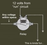
I have two questions. First, I have a bad GPC Relay and I happen to have three or four spare, relays that are the same as the GP Relay except they are 24 volts in and out. I also have 2 sets of 24V glow plugs. Can anyone tell me if I can do a manual glow plug set up WITH a 24V relay?

Also, I broke my fuel bleeder screw and none of the parts stores carry anything like that. Does anyone know where I can find either a replacement or something like it? Im about to go to Fastenal and have them make a threaded valve that I can use to bleed the system.

Thanks in Avance.

Mike
 

Warthog

Moderator
Super Moderator
Steel Soldiers Supporter
13,774
224
63
Location
OKC, OK
The stock glowplug relay has a 12v coil and is switching 24v. Also the relay doesn't use the mounting bracket/housing as a ground.

What is the coil votage on your spares?

If it is 24v then you would have to tap into the 24v power to energize the relay. That means you would totally bypass the 12v Glowplug Controller and associated wiring.

You can run 24v glowplugs by bypassing the resistor on the firewall.

If you do make any changes from stock, PLEASE document them and pass that info onto any future owner. It makes it easier for us to help diagnose problems when we assume the truck is stock and the new owner has no clue.
 

ssgtcampbell77

Staff Sergeant
227
1
0
Location
St Louis MO
Gotcha, will do. If i bypass that Glow Plug module, will it mess with any of the other electronics in the truck? I don't think it will as looking at the schematics there is nothing else associated however, the TMs are know for not being 100% accurate.

What your telling me is the stock gp relay is taking 12V and switching to 24? Im confused, as I trace everything and read the schematics, it seems that the relay is taking in 24V and putting out 12 to the glow plugs. Please correct me if Im wrong.

I will test the voltage on the spares I have tommorow but I pulled them out of a junk 5 ton years ago that had a complete 24V system. Thanks for the info.

Mike
 

Warthog

Moderator
Super Moderator
Steel Soldiers Supporter
13,774
224
63
Location
OKC, OK
As it has been discussed many times,

the stock system takes the 24v, passes it thru the resistor, then the relay and then feeds the glowplugs.

The way it is designed, "IF" all the glowplugs are functioning, the 24v is reduced to 12v by the resistor pack and the glowplugs resistance. If it is working properly the glowplugs see 24v at first, heatup and the voltage drops to 12v.

If one glow plug burns out then a little more voltage is supplied to the other 7, Then next one burns out and even more voltage, until the last "good" plug is receiving the entire 24v and it dies a very painful death.

The relay could careless what voltage is being switched, as long as it is within it design range.

The part that matters is the coil voltage. They will only work with the voltage they where designed for.

So there are two parts to the relay. The coil that energises (low amperage) which closes the contacts (high amperage).

And the contact circuit. Just a set of contacts that allows higher amperage current to flow.

Bypassing the glowplug module will not affect any of the other circuits.

Sure seems easier to just buy the correct parts and put it back to stock. So much easier to work on in the future as the manuals where written for a stock system.
 

tamecrow

Member
121
0
16
Location
Nova Scotia
The stock glowplug relay has a 12v coil and is switching 24v.
How could it be switching 24 volts if the resistor has the voltage dropped to 12 volts before it reaches the glow plug relay? In a properly working system the glow plugs never receive 24 volts unless the resistor is shorted.
 
Last edited:

Warthog

Moderator
Super Moderator
Steel Soldiers Supporter
13,774
224
63
Location
OKC, OK
In laymans terms:

There is no voltage drop until current flows. 24v is sitting there waiting to be switched. If the glowplugs aren't working then the whole 24v is fed to the connectors at the plugs.

The resistor only has 3 ohnms and doesn't drop the voltage that much.

Each plug has a resistance of 1.5~3 ohms and provide much more resistance to drop the voltage. They all work together.

In a previous life I was in the electrical engineering world. I'm not being rude but can I ask you back ground?
 
Last edited:

1stSarge

Member
428
4
18
Location
Mount Vernon, Ohio
Think of this theory as an orifice in a hydro system. A one inch pipe restricted down to an orifice of, say, 1/8th inch in the middle.

If we install a pressure gauge on either side of the orifice, we will see that the pressure on both sides of the orifice will be the same with no water flowing.

As soon as we turn the water on, there will be a slight drop in the pressure before the orifice, but a huge drop in pressure AFTER the orifice.

Looking at both gauges we will see the “difference” translated back to real life as the “voltage drop”.

Not truly an accurate model of how it works, but makes it way more understandable.

Kinda see?
 

tamecrow

Member
121
0
16
Location
Nova Scotia
Warthog, I understand what you're saying about the firewall resistor working in conjunction with the resistance of the glow plugs.

But what I don't get is this, You said: "The stock glow plug relay has a 12v coil and is switching 24v".

At what time during the normal glow cycle does the glow plug relay receive 24v? Maybe I'm reading your posts wrong, but I can't see how you're getting 24 volts at the glow plug relay in a properly functioning circuit.
 

ssgtcampbell77

Staff Sergeant
227
1
0
Location
St Louis MO
As it has been discussed many times,

the stock system takes the 24v, passes it thru the resistor, then the relay and then feeds the glowplugs.

The way it is designed, "IF" all the glowplugs are functioning, the 24v is reduced to 12v by the resistor pack and the glowplugs resistance. If it is working properly the glowplugs see 24v at first, heatup and the voltage drops to 12v.

If one glow plug burns out then a little more voltage is supplied to the other 7, Then next one burns out and even more voltage, until the last "good" plug is receiving the entire 24v and it dies a very painful death.

The relay could careless what voltage is being switched, as long as it is within it design range.

The part that matters is the coil voltage. They will only work with the voltage they where designed for.

So there are two parts to the relay. The coil that energises (low amperage) which closes the contacts (high amperage).

And the contact circuit. Just a set of contacts that allows higher amperage current to flow.

Bypassing the glowplug module will not affect any of the other circuits.

Sure seems easier to just buy the correct parts and put it back to stock. So much easier to work on in the future as the manuals where written for a stock system.
I agree that it would be easier to stay stock, it just seems a waste that I have a couple extra relays and 50-something 24V plugs.

Im gonna do the manual push button conversion and I was just wondering if I could get away with going to 24V plugs.
 

1stSarge

Member
428
4
18
Location
Mount Vernon, Ohio
Drew them just for you... :)


What we are trying to figure out is if your relays will work. The coil part in the previous pic HAS to be 12 volt to work in the system. 24 volt will not work. Do they have a model number or any other identification on them?
 

1stSarge

Member
428
4
18
Location
Mount Vernon, Ohio
You ever meet one of those annoying guys that when ever he talks he has to get out a piece of paper and a pencil to describe something? Yeah, that’s me.

If you could measure the resistance across the coils that might give us a clue as well (OHMS across the two smaller terminals).
 

Attachments

Last edited:

doghead

4 Star General /Moderator
Staff member
Super Moderator
Steel Soldiers Supporter
26,247
1,172
113
Location
NY
Awe gee, now you done it...


The water pictures compared to the schematics, are technically "backward". When the water circuit is "closed" there is no pressure difference. But the schematic needs to have a "closed"(or complete) circuit, to create a voltage difference.

The simple fact is, the resistors do nothing, until the electric circuit is complete(closed).


Here's a link with some basics and some pretty good examples.
http://www.autoshop101.com/forms/elec11.pdf
 

Attachments

Last edited:

ssgtcampbell77

Staff Sergeant
227
1
0
Location
St Louis MO
aua Bottom line is: I need to just buy new plugs. I hate having stuff I can't use!!! Anybody know where I can get a fuel bleeder screw? The Chevy dealer wants to charge me $25 for a plastic friggin screw!!! Im just gonna buy a new relay and plugs, then I have to figure out how to bleed the fuel system without a bleeder screw!!!!
 

DonK

New member
92
0
0
Location
Social Circle,GA
Use a NAPA ST-85 for the GP relay. 12vdc Coil, switches the 24vdc to the GP's...
Use AC60G for the Glow plugs. You'll have to grind the connectors to make them fit...Worked great for me
 
Top