GasTurbineTech
Member
- 59
- 9
- 8
- Location
- kingston/ NH
I am in the middle of doing my 4L80e Conversion and will do a write up on that part of the project, but I was unable to find anything on modify the stock shifter. Here is my adventure...
Modification of 3 Speed Shifter:
One of my initial concerns with the 4-speed conversion was the shifter mechanism. I am very turned off with the price that the market is getting for these ($500-$700 in 2019), the controller is expensive, but some options at least give us options. I see no reason for this pricing beyond fake supply and demand and I saw no reason the 3 speed can’t be made to work.
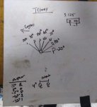
With the 2 transmissions out, I used an angle finder to map the angles as the gear change lever is moved through the detents. 3 main differences (Park is a large angular change, 7 positions vs 5, and angle spacing) were noted. I would have been ok with only OD and D, but as it turned out, I was able to get all 7.
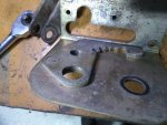
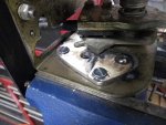
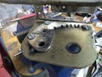
After removing the stock shift gate (this is the piece of metal that has the Detents that lock the shifter in position that lines up with the internal Transmission Detents) I was able to create my own template and gates. This worked a lot easier than I anticipated. I expected to have to use CAD to layout a gate and get a machine shop to cut it out but was able to make it on my workbench with an angle grinder and metal bandsaw. Stock and replacements are both 3/16” mild steel (I also expected it to be hardened, but it is not, and I really don’t think it needs to be after mulling the idea of making the new one hard). I had steel scraps from an old weight bench, but Tractor Supply, Lowes, Home Depot, etc for under $20.
· First Step- install ¼” Rivnuts (I bought a $12 kit at Harbor Freight). Stock configuration with uncaptured nuts on the bottom is silly.
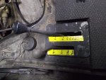
· I used a magnetic Angle finder on both transmission shift levers (I used the TH400 Shift lever on the new 4L80e) in all the detent positions and on the stock installed shift mechanism (see picture with measurements). This would be key to making the REV1 Gate later.
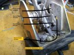
· I removed the Shifter mechanism (the linkages were already removed during tranny swap steps)
· Removed the Shift Gate Light & the neutral safety switch
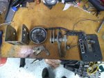
· Disassembled the entire mechanism. There are 2 Roll Pins, roll pin punches are recommended, especially for the transfer case one, it is tiny.
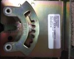
· The shift gate is secured to the body by 3 rolled rivets- Drill & Grind them to remove gate
· I used the Old Gate as a template to create new 7 position gates (rev1). Note- there was the Neutral safety hole AND a reverse light hole already. The shifter rod has tabs to activate both of these.
o REV1 Gate
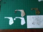
· Both new gates were drawn out on paper first. I laid a piece of paper over the stock gate and traced the basic shape, all 5 holes and the stock gate positions. Laying this paper of the main shift body, I lined the 5 holes up and was able to trace the hole for the pivot arm of the shifter, key step as this is a master measurement that is needed to get the Arcs for the new gates correct. I then used a compass to get the Inner and Outer Arcs drawn on the template, then used a protractor to mark the Cuts.
· In my new Gate, I used the Reverse hole position for the new location for Neutral safety switch position (where park is now)
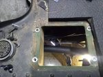
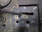
· Based upon my Rev1 and angle measurements, I enlarged the shift area rectangle in the body and the top plate. I enlarged the back side (towards the rear of truck) only by maybe ¾”, this eliminate one of the bolts that holds the top plate on the body, but 2 bolts are more then enough for a nonstructural member in my opinion.
· This still only allowed me to get 4 maybe 5 of the gate positions on m Rev1 gate. This was largely driven by the huge angular thrown with the P to R positions.
· I reassembled the mechanism & installed the Rev1 Shifter and re-hooked up the stock linkage J bolt, moving the trunnion on the J bolt. While this worked, almost as expected, I was barley getting in to the D position and the whole thing was wonky and not confidence inspiring! I then drilled a 2[SUP]nd[/SUP] hole in the Transmission Shift Lever. Stock hole was 3.125” CL to CL. I went to 2” CL to CL, this is what I ended up using in the final product.
· This New shorter throw lever would not work at all. Too much play in the whole assemble. Back to the Drawing Board
o Rev2 Gate
· I ordered a Military 4L80e shift jack assembly (P/N: 12447182, E-bay @ $11.39 shipped!). This uses to rods and a second pivot arm vs the TH400 J-Bolt assembly.
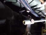
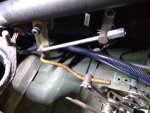
· The new Shift Lever Bracket installs through 2 of the pan bolts. Once installed, I made up 2 rods with Swivel Trunnions (needed 1additional from Kascar Item# 6001696 @$3.22). 1 rod is a straight piece of 3/8-18 threaded rod connecting the lower hole on the Shift Lever Bracket, to the New Hole in the shift lever arm, this is 7-3/8” CL to CL. I used nuts on the end of this to lock it but will end up peening the rod when I finalize & paint it. The 2[SUP]nd[/SUP] was an offset 3/8 threaded rod, connecting the top hole back to the Shifter Mechanism. Easily bent in my bench vise.
· Now that I had the Linkage straightened out, I Shifted the mechanism while using a Sharpie & the angle finder to move the shift lever with the button fully depressed to mark the REV1 Gate, that was still installed, (also measured the angles to verify later) when the transmission engaged each gear position. I remove the shifter mechanism at this point
· I created the REV2 template, then the metal gate, using these marks and validating them with the angle readings (tough to get 100% accuracy with the sharpie). The Lever Bracket & Shorter Arm allowed all 7 gear positions in the REV2 Gate fitting in the “lengthened” shifter slot (would be worth checking if the stock slot might not be “lengthened”
· After cutting the rough shape, use small file, grinder, Dremel, etc. to fine to the Detents. I used the shifter to ensure a good fit.
· The stock gate was attached to the housing with 3 special rivets. .500” thin heads on ~.280 rivets that were peened over. My initial plan was to weld back through these holes, but instead found that ¼-20 bolts were more than sufficient to hold it in place. There were 3, but the hole in the back end is now covered by the 2 or 1 gear position. I found that with the through bolts there is no play & with the bolts being at the front end, where the Park is, I am fine with it. IF I ever spot movement, I will simply spot weld it in place. I reefed on it with out the shift linkage in place, and where my detents are deeper then stock, it was very secure.
· Drill out the new hole for the neutral safety (this was the exact position in the TH400 gate then was drilled & tapped for the reverse light switch). The neutral safety is 9/16”-18, the reverse is bigger. I drilled the reverse hole undersized for now, if I ever want to add a reverse light switch, it will be easy to do.
· Reassemble and install.
· Check the linkage to ensure the transmission matches the new gate. You do not want to put pressure on the transmission detents. I actually did a semi assembly incase I needed to tweak.
I still have to build a new LED backlit position indicator, but that will come later, as well a repaint and re-rubber the top plate once I complete the whole 4L80e Swap.
In full disclosure, I had this thing in and out many times, hence the early comment about the Rivnuts! Waiting for parts (9/16 tap, trunnions, etc) and other parts of the transmission swap made this take a few days longer, but overall, I think this is a more then viable option. I will update this as I complete the finishing touches and if I end up having any problems. Overall, less then $15 for this modification
Take away, if you are like me and want to do it, save the money and mod your Shifter.



Attachments
-
77.6 KB Views: 120


