Here we go. First off, where is your 3 way valve handle pointing. I know you said that all you did way change filters, but I am am not 100% sure if this set ran before you started changing filters. So, If your handle is not looking like this attached picture, move it. Simple problem that has stumped lots of folks, including me.
If the handle is in the right position, lets try this. You wrote this.
I went and checked the pumps themselves to see if they worked ie 24vdc Postive straight to the pump. They thumped quickly then slowed down as if under pressure but no fuel came out the bleeders/
So what I want you to do is look at the last electric fuel pump.
View attachment 857092
As you can see from the diagram, fuel is drawn from the tank, through the 3 way valve, to the B2, (first E-pump) then to and through the B3 and the fuel filter/strainer assy. Follow the hose on the output side of B3 over to the Strainer/filter assy and remove it. Put the end of the hose into a container. Push in CB1, (DC Control Circuit Breaker). Then place the S2, (start/run/stop switch) in the run position. Then place the S7, (Battle Short Switch in the Up/On position. At this time you should hear and feel the B2 &B3 come on. They should run FAST. Also know, that if the hose is not wedged into the container , the hose could come out, due to the out rush of fuel, and make a real big mess. If the pumps come on, and run fast, let them run and fill up your small, (QT will do) container. That should bleed out all air from the tank to the hose end. I use a glass container, so I can look at the fuel and see how funky it is. If this in fact happens, and you get fuel, then we need to go a step farther.
Turn off the pumps with S2. Leave the CB1 pushed in and S7 in the up position for the duration of this testing. Hook the hose back up. Turn the S2 back on.
View attachment 857093
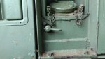
Open the petcock (Item #5) on the fuel strainer. Fuel should come out at a very healthy stream. Use your handy container to catch it. If there is air bubbles, let it run until you only have fuel coming out. Then go to the other petcock on the filter to the left. Open it and see if fuel comes out. If so, go to the output side of the fuel filter/strainer head, (Item #17) and loosen the hose connected there. You should get maybe some air and then fuel. When its just fuel, tighten the hose up. Turn off the S2.
View attachment 857094
Trace the fuel line from the output side of the filter/strainer to the L2, (Fuel Shut Off Solenoid) item #15. Lossen the input hose, and turn on S2. Should get fuel coming out. Do have a large rag handy. Then tighten the input hose back up.If your fuel comes out, we now go to your mysterious DAY TANK.
The day tank is there for a real good reason. It keeps, (if its working right) the set from running out of fuel and emptying the fuel from the IP to the injectors, running bone dry. How does that work? The FL1 & FL2 switch. Item #16. There are two switches built into it. The switch can come with one or two floats on the switch. The one switch, FL1, turns the set off when it senses low fuel level in the day tank. That stops the set from running dry. The FL2 switch senses that the day tank is no longer full, and opens the L2 solenoid, to allow fuel to be pumped into the day tank, replenishing the supply of fuel in the day tank, from the set tank, (belly tank). When the FL2 senses that the tank is full, it closes L2.
Lesson over.
So, if you are getting fuel up to the L2, turn S2 off. Then remove the J33, (C-Plug on top of the FL1/FL2 switch. Then unscrew/remove the switch from the day tank. (Is the switch wet with fuel?) Screw the J33 back in. Here its good to have a helper. Hold the switch in one hand, and raise the float, or floats completely up. Have your trusted assistant place the S2 in the run position. Then lower the top float, (if there is two floats or just the one float) a bit, and the fuel pumps SHOULD come on. If not, continue to lower the float. If its a two float switch, just let the float go as far as it can. The pumps should come on, and fuel should fill the day tank. WARNING! If you pause to drink a beer, or something like that, the day tank WILL over flow in a hurry, as you have the day tank switch in your hand. It will happen faster then you can think about it. If not, we need to test first the Float switch, and then the CR-27 diode and the L2.
Let go this far, and you can look the test up in the -12 TM, (go to PDF reader page 161 and 162.) or tell me to stop, or walk you through the procedures.
Go for it!