• Steel Soldiers now has a few new forums, read more about it at: New Munitions Forums!

  • Microsoft MSN, Live, Hotmail, Outlook email users may not be receiving emails. We are working to resolve this issue. Please add support@steelsoldiers.com to your trusted contacts.


3D Printed Tool for Hub Shimming/Setup

88atlas07

New member
14
4
3
Location
Springtown, Texas
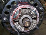
I'm the guy on the LMTV FB asking all the measurement questions. I'm about two weeks out from doing the 3.07 gears (still waiting on seals etc) and after a lot of research plan on doing the TM method of measurement, although I have ordered a spare hub that I'll cut down and try the open hub method everyone is talking about. The Army style of measurement is simple to understand as per Neil's Video and seems fail safe if you take your time. The open hub method still leaves me with questions....how exactly do I go about measuring gear lash with it all clamped up? There are pics floating around with feeler gauges being used but doesn't specify on what.

I'm starting to feel retarded because I don't understand the clamped method at all. Maybe once I take it all apart it'll make better sense. So far definitely going the TM preferred method as Neil demonstrated in his video, but will confirm the clamped method while I have it all apart if we can figure out what to measure.
 

Attachments

Smike740

Member
Steel Soldiers Supporter
199
13
18
Location
Columbus, Ohio
The cut down hub holds the spider gears in the hub similar to what is shown in your picture. You rotate the hub so one of the spider gears is at the 6 o clock position and use a dial indicator with the plunger against the gear tooth to measure the lash. You rotate the spider gear to take up the lash set the dial indicator on zero and then rotate the spider gear in the other direction and measure the lash. Very similar to how you measure the lash on a ring and pinion set up.
 

coachgeo

Well-known member
4,955
3,325
113
Location
North of Cincy OH
The cut down hub holds the spider gears in the hub similar to what is shown in your picture. You rotate the hub so one of the spider gears is at the 6 o clock position and use a dial indicator with the plunger against the gear tooth to measure the lash. You rotate the spider gear to take up the lash set the dial indicator on zero and then rotate the spider gear in the other direction and measure the lash. Very similar to how you measure the lash on a ring and pinion set up.
Measure lash like this?


if so how do you correlate shim size needed to reduce this lash?
 

Awesomeness

Well-known member
Steel Soldiers Supporter
1,811
1,509
113
Location
Orlando, FL
The purpose of the open hub method is that you actually get to measure it directly. You measure it, and know exactly how it stands.

The TM method is a theoretical "dead reckoning". You take it apart, measure all the parts, add them up mathematically, and the answer should be close to how it all sits when it's put together and you can't see it. It's apparently "good enough for government work", but obviously introduces some tolerances because nothing fits together exactly the way the parts are measured, plus the added potential for human error in the calculations.

Also keep in mind that if your hubs are running cool, aren't making any noise, and don't have any other indications of issues, it's not unreasonable to just leave them alone. Even if you're swapping 3.07:1 gears, you don't have to mess with the hubs... you can just put them back together the same way you took them apart. Or leave that project for another day, since they are easy to get to.
 
Top
AdBlock Detected

We get it, advertisements are annoying!

Sure, ad-blocking software does a great job at blocking ads, but it also blocks useful features of our website like our supporting vendors. Their ads help keep Steel Soldiers going. Please consider disabling your ad blockers for the site. Thanks!

I've Disabled AdBlock
No Thanks