• Steel Soldiers now has a few new forums, read more about it at: New Munitions Forums!

  • Microsoft MSN, Live, Hotmail, Outlook email users may not be receiving emails. We are working to resolve this issue. Please add support@steelsoldiers.com to your trusted contacts.

3rd Battery and Isolator

stationjj

Member
263
1
18
Location
Middle Tennessee
Update on adding 3rd battery and battery isolator to my M1009. I think I got everything installed correctly. I did a test and nothing shorted out, or blew up, and my primary battery bank seems to re-charge as normal.

Overall the install was easy and straight forward even for an amateur DC Electrical guy. I love projects like these on the CUCV. I always learn something.

The hardest issue I had was finding a mounting place for the isolator near the current batteries on the passenger side. I am using a NOCO 140 amp Isolator I got off Amazon. I ended up mounting the isolator under the front battery tray. It was a tight fit, and I had to create plate for the battery isolator to mount too. Picture Below.

I do have a few questions concerning isolator.

I how can I verify the isolator is recharging 3rd battery? Add a volt meter and monitor? I plan to add a digital volt meter.

In recharging the isolator gives priority to Primary battery before the 2nd battery? My thought is yes. Want to verify.

I wanted to update this post as future reference. When I started this project I found the other posts confusing for my level of DC electrical knowledge.
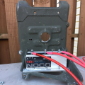
86be5142-7322-43a5-8cc1-c6c2d30c9880.png

Thanks

John
 
Last edited:

MarcusOReallyus

Well-known member
4,524
816
113
Location
Virginia
Update on adding 3rd battery and battery isolator to my M1009. I think I got everything installed correctly. I did a test and nothing shorted out, or blew up, and my primary battery bank seems to re-charge as normal.
Sounds good!


The hardest issue I had was finding a mounting place for the isolator near the current batteries on the passenger side. I am using a NOCO 140 amp Isolator I got off Amazon. I ended up mounting the isolator under the front battery tray. It was a tight fit, and I had to create plate for the battery isolator to mount too. Picture Below.
Very nice! :beer:

Well, except for that picture! How about a full-size version! The forum will provide a thumbnail version in the post, and we can click on it to see the big version.


I how can I verify the isolator is recharging 3rd battery? Add a volt meter and monitor? I plan to add a digital volt meter.
Yep. That's what I would do.


In recharging the isolator gives priority to Primary battery before the 2nd battery? My thought is yes. Want to verify.

No, not with isolators I've seen. It just divides the circuit, but it's not intelligent about it. When one battery is fully charged, it will offer more resistance, so there will be less charging current there, and more current will flow to the battery with the lesser charge. So, really, it favors whichever battery has the lower charge.

Think of an isolator as a couple of check valves in a plumbing manifold, set up as a T arrangement. You have water flowing into the post of the T (the upright), and then flowing out each arm. In each arm is a check valve (diode) that prevents the water from flowing back into the arm. It can only go out. Your alternator is the "pump", connected to the post of the T, and your batteries are tanks, connected to the arms. The tanks are sealed. As you pump water in through the T, it flows out both arms and into the tanks. If one is more empty than the other, there will be less back pressure (resistance) there, and more water will flow that way. As the tanks fill, the pressure will gradually equalize, and there will be equal flow.

Then you open a valve on one of the tanks (turn on a switch and use electricity) and the pump starts working to replace it.

The check valves make sure that draining one tank will not drain the other.


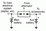
Here's a diagram I found online:

battery isolator schematic.gif

See the "arrowheads" inside the box? Those are diodes, the "check valves" in my plumbing story. Electricity can only flow in the direction of the arrow. Coming the other way, it's a blank wall - no entrance. So, the electricity flows from the alternator (the pump) to the batteries (tanks), and never the other way.

Clear as mud? :mrgreen:

Thanks for the update! :beer:
 
Last edited:

ke5eua

Well-known member
2,568
41
48
Location
Baton Rouge (Central), LA
Sounds good!


Very nice! :beer:

Well, except for that picture! How about a full-size version! The forum will provide a thumbnail version in the post, and we can click on it to see the big version.


Yep. That's what I would do.


No, not with isolators I've seen. It just divides the circuit, but it's not intelligent about it. When one battery is fully charged, it will offer more resistance, so there will be less charging current there, and more current will flow to the battery with the lesser charge. So, really, it favors whichever battery has the lower charge.

Think of an isolator as a couple of check valves in a plumbing manifold, set up as a T arrangement. You have water flowing into the post of the T (the upright), and then flowing out each arm. In each arm is a check valve (diode) that prevents the water from flowing back into the arm. It can only go out. Your alternator is the "pump", connected to the post of the T, and your batteries are tanks, connected to the arms. The tanks are sealed. As you pump water in through the T, it flows out both arms and into the tanks. If one is more empty than the other, there will be less back pressure (resistance) there, and more water will flow that way. As the tanks fill, the pressure will gradually equalize, and there will be equal flow.

Then you open a valve on one of the tanks (turn on a switch and use electricity) and the pump starts working to replace it.

The check valves make sure that draining one tank will not drain the other.


Here's a diagram I found online:

View attachment 549881

See the "arrowheads" inside the box? Those are diodes, the "check valves" in my plumbing story. Electricity can only flow in the direction of the arrow. Coming the other way, it's a blank wall - no entrance. So, the electricity flows from the alternator (the pump) to the batteries (tanks), and never the other way.

Clear as mud? :mrgreen:

Thanks for the update! :beer:
Problem with solid state isolators is that there is a reverse voltage on diodes. It's usually less than 1 volt but if you don't use the vehicle every day you can still end up with dead batteries.
 

MarcusOReallyus

Well-known member
4,524
816
113
Location
Virginia
There is no reason to quote an entire post simply to respond to one point, particularly when your response doesn't address anything you quoted.

That's why there's a "Reply" button and a "Reply to Thread" button.
 

dmilkman589

Member
181
1
18
Location
troy, ny
Wouldn't it Make more since to just run a positive/isolated ground and use the back battery for all your accessories? Then you don't have to drop 400 dollars every time you want new batteries.
 

MarcusOReallyus

Well-known member
4,524
816
113
Location
Virginia
That works in theory, but it's far from the best solution. It's really difficult to maintain an isolated ground, especially if you are trying to run radio equipment on it. Whether CB or ham, most antennas you can buy expect the vehicle ground to be the same as the radio ground. There are ways around it, but it's gets sticky.

That is the LAST approach I'd recommend, really, though it depends on what you are running as accessories.

Even if you make it work, if you sell the vehicle the next guy might get a nasty surprise.
 
Top
AdBlock Detected

We get it, advertisements are annoying!

Sure, ad-blocking software does a great job at blocking ads, but it also blocks useful features of our website like our supporting vendors. Their ads help keep Steel Soldiers going. Please consider disabling your ad blockers for the site. Thanks!

I've Disabled AdBlock
No Thanks