• Steel Soldiers now has a few new forums, read more about it at: New Munitions Forums!

  • Microsoft MSN, Live, Hotmail, Outlook email users may not be receiving emails. We are working to resolve this issue. Please add support@steelsoldiers.com to your trusted contacts.

6L80 in my M998

Mogman

Moderator
Staff member
Moderator
Steel Soldiers Supporter
7,017
9,694
113
Location
Papalote, TX
EDIT, as you read this thread I ended up using a 6L80 as the 6L90 was toast and the 6L80 has the same output shaft as the 4L80/3L80.
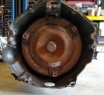
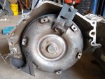
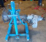
I was at a machine shop auction the other day and picked up a 6L90 with a MP1626XHD transfer case, it is complete with T/C, the front shaft, cooler lines and shift linkage so it looks like it was pulled out of a salvage vehicle.

So the wheels started turning and after some research it does look possible to install one in a HMMWV, there is one company selling stand alone controllers that only MUST have RPM and TPS to operate, it is actually about 1/2" shorter from the bell housing to the transfer case adapter VS a 4L80E which is amazing for a 6 speed, of course that little advantage is lost unless one adapts a smaller transfer case.

It has double overdrive with 6th being 0.677:1 VS 0.75:1 for the 4th in the 4L80E (the Allison is 0.614:1 in 6th)

It is much more efficient than that dinosaur 4L80 (This means more of the puny Detroit input HP will get to the output)

It has a MUCH lower 1st gear than the 4L80, 4.030:1 VS 2.480:1 but because it is a 6 speed the ratios are actually closer together than the 4L80.

Adding a ton of power to my DuraVee made a big difference but the 6 speed Allison with its double overdrive was the game changer for sure.


I will swap out the electric shift transfer case for one of the manual MP1226XHD units I have here. (the electric shift MP transfer cases have trouble in stand alone without a matching ECM)

I believe I will be the first to install a 6L80/90 in a HMMWV
 
Last edited:

Mogman

Moderator
Staff member
Moderator
Steel Soldiers Supporter
7,017
9,694
113
Location
Papalote, TX
I have been gathering more information and have started to get the mock-up ready.

This is an early 6L (I think this is common in the 06-11 year models) so all of the 6 Gen 1 bolt holes line up

the only coupling issues are some .4" spacers must be used between the flex plate and the converter.

Also the 6L90 converter has a 11.1" (or 11.07 depending on information source) bolt circle and there are two basic Gen 1 flex plates, are 11.5" and a 10.75"

So all that needs to be done there is to elongate the holes to match, I have both flex plates and because the 10.75" has a thicker therefore smaller counter weight welded to the flex plate it appears it will be much easier to mod the 10.75" as there will be no interference from the counter weight.

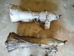
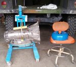
Here is the 6L90/MP1625HDX next to the TH400/NP218, despite what the camera seems to show the 6L90/MP is only 4" longer than the TH400/NP from the bell housing surface to the center of the rear U joint.
IMG_20210914_135050790.jpg

Of course the slip joint is fully engaged on the 6L90, I wish I had a 4L80/NP242 to compare it with, I may luck out and be able to use an A2 rear shaft.
That TH400 came out of the DuraVee, this is the engine which I am fortunate to have so I can mock up before trying to install.
IMG_20210913_124703778.jpg
It is a damn shame, this engine only had 6K on it when the motor pool decided to pull off the injection pump and then at some point pushed it outdoors without the air horn on the intake, on the HMMWV this is directly under the drip line on the rear of the hood.
Of course this was obvious to everyone so I got it relatively cheap and I was planning the Duramax conversion anyway and it gives me something to use for the mock up, would be a little handier if I could rotate it.

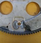
One of my concerns is the relief area for the starter nose is cast into the converter housing on the 6L90 and that may be an area that may need to be modified, but again the mock up will show this.
IMG_20210914_135107081.jpg
IMG_20210914_135702202.jpg
 
Last edited:

Mogman

Moderator
Staff member
Moderator
Steel Soldiers Supporter
7,017
9,694
113
Location
Papalote, TX
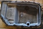
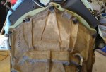
Well this is real bad, pulled the pan, I am going to have to get some estimates but for now this project is in jeopardy, my fixed income does present some limitations.
IMG_20210915_113448892.jpg
 
Last edited:

Mogman

Moderator
Staff member
Moderator
Steel Soldiers Supporter
7,017
9,694
113
Location
Papalote, TX
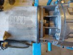
OK so I have pretty much worked out the details of coupling the 6.2L to the 6L80/90 which is the same in every respect, only the 90 has a larger 29 spline output shaft which limits the transfer case options to the later MP series and some earlier NP boxes from the late 90s to the mid 2000s (as in 2006 or so)

The 80 series has a 32 spline output shaft and the transmission is about 1.7" shorter than the 90 series

Also it looks like the re-clocking ring I fabricated for the 700R4/NP218 will also work on the 6L80/NP218, so I am seeing if I can swap a 90 series core for an 80 series transmission.

I already know that the MP1226/MP1626 transfer case can be installed in a HMMWV because that is what is behind the Allison 1000 in the DuraVee so nothing to prove there except confirming again that it is a bitch.

With the 6L80/NP218 (242 should work the same) it will have the correct mounting tabs for the exhaust for instance so the project should require less fabrication and the transfer case shifter will have the correct gear placement labels, so on with the details!
 
Last edited:
Mogman

Moderator
Staff member
Moderator
Steel Soldiers Supporter
7,017
9,694
113
Location
Papalote, TX
Unlike the first impression the adapter kit from Lakewood (15901LKW) is required to space the transmission back 0.4" is along with the 0.4" spacers for the converter to flex plate connection.
here is the "kit"
drill hole.jpg

This kit is actually designed to help with some Gen 1 and 2 transmissions to Gen 3 up engines but will be necessary for our Gen 1 engine to Gen 3 transmission.
The parts needed are the converter housing adapter, 3 of the converter spacers and 3 of the M10-1.5X25 long converter bolts, the 2 extended engine dowels and that is all. the extended converter housing bolts are metric and the 6.2L holes are 3/8" (requires 6, 3/8X1 3/4" and 1, 3/8X1 1/4" flanged grade 8 bolts)
OK next we will deal with converter/flex plate.
 
Last edited:

Mogman

Moderator
Staff member
Moderator
Steel Soldiers Supporter
7,017
9,694
113
Location
Papalote, TX
OK the flex plate,
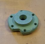
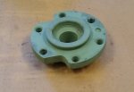
I decided it would be prudent to weld (tig) the spacers to the flex plate this does two things, first it makes coupling up the converter MUCH easier as one does not have to deal with trying to reach around between the flex plate and the converter to fumble the spacers in place while trying to start the converter bolts.

And secondly it removes all possible "slop" from the filing and fitting operation adapting the Gen 1 Flex plate the the Gen 3 converter (remember I am using a 700R4 flex plate that has a 10.75" bolt circle and the converter has a 11" bolt circle. (the original flex plate has a 11.5" bolt circle and would be much more difficult to fit as the counter weight is in the way)

EDIT, the part numbers for the 700R4 flex plate are ATP Z135 and Pioneer FRA143.


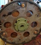
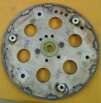
BUT to do this the flex plate must be perfectly aligned with the converter and one practical way to do this is to bolt it to the crankshaft, but this leaves allot to desire as far as accessibility to the hole filing/fitting and welding operations, so my answer was to cut off the rear of a junk Gen1 350 crankshaft, virtually all Gen 1 GM cranks had the same flywheel flange profile.
IMG_20210922_133440249.jpgIMG_20210922_133445153.jpg

So now it was easier to see how much to file (elongate) the flex plate holes.
IMG_20210922_132809168.jpg
AND I can easily see that the converter pilot is penetrating far enough into the back of the crankshaft (what actually aligns the crankshaft with the transmission input shaft), and also can see that there is no interference between the converter and the flex plate/crankshaft bolts.
IMG_20210922_132932152.jpg

So now I can weld up the spacers and that part of the conversion is worked out, OVER!
IMG_20210922_133213361.jpgIMG_20210922_133400325.jpg
next will be the converter housing/engine coupling!
 
Last edited:

Mullaney

Well-known member
Steel Soldiers Supporter
Supporting Vendor
7,769
19,877
113
Location
Charlotte NC
OK the flex plate,
I decided it would be prudent to weld (tig) the spacers to the flex plate this does two things, first it makes coupling up the converter MUCH easier as one does not have to deal with trying to reach around between the flex plate and the converter to fumble the spacers in place while trying to start the converter bolts.

And secondly it removes all possible "slop" from the filing and fitting operation adapting the Gen 1 Flex plate the the Gen 3 converter (remember I am using a 700R4 flex plate that has a 10.75" bolt circle and the converter has a 11" bolt circle. (the original flex plate has a 11.5" bolt circle and would be much more difficult to fit as the counter weight is in the way)

BUT to do this the flex plate must be perfectly aligned with the converter and one practical way to do this is to bolt it to the crankshaft, but this leaves allot to desire as far as accessibility to the hole filing/fitting and welding operations, so my answer was to cut off the rear of a junk Gen1 350 crankshaft, virtually all Gen 1 GM cranks had the same flywheel flange profile.
View attachment 845992View attachment 845993

So now it was easier to see how much to file (elongate) the flex plate holes.
View attachment 845994
AND I can easily see that the converter pilot is penetrating far enough into the back of the crankshaft (what actually aligns the crankshaft with the transmission input shaft, and also can see that there is no interference between the converter and the flex plate/crankshaft bolts.
View attachment 845995

So now I can weld up the spacers and that part of the conversion is worked out!
View attachment 845996View attachment 845997
next will be the converter housing/engine coupling!
.
Dang!

Perfectly Centered and everything... Really well thought out!
 

McSpeed

Well-known member
333
293
63
Location
Palmer, AK
Maybe you mentioned it - but it is my understanding it it crucial to get a diesel spec torque converter when doing these swaps.

Keep up the great work - I came across one of these and passed on it since I found no credible info from successful swaps and I wasn't ready to blaze my own new trails.
 

Mogman

Moderator
Staff member
Moderator
Steel Soldiers Supporter
7,017
9,694
113
Location
Papalote, TX
Maybe you mentioned it - but it is my understanding it it crucial to get a diesel spec torque converter when doing these swaps.

Keep up the great work - I came across one of these and passed on it since I found no credible info from successful swaps and I wasn't ready to blaze my own new trails.
EDIT, I ended up using a custom low stall T/C in this build.
 
Last edited:

Mogman

Moderator
Staff member
Moderator
Steel Soldiers Supporter
7,017
9,694
113
Location
Papalote, TX
OK, now for the converter housing!
Because I have an early model 6L that does not have the later model "LS" bolt pattern, all 6 of the "legacy" converter housing bolts line up so one of the threaded holes in the adapter needs to be drilled out (your mileage may very if you have a later converter housing on your 6L trans.)
EDIT, this picture shows all the parts that come with the kit, all I used are the adapter plate, 3 converter spacers and extended converter screws and the 2 extended dowel pins.
drill hole.jpg
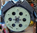
So here is the classic view of the Gen 1 block, it basically would look the same if it was an early SB or BB gasser, only the diesel flex plate has a different teeth per inch so the diesel 139 tooth flex plate is the exactly the same dia. as the 168 tooth gasser flex plate.
IMG_20210923_150530280.jpg
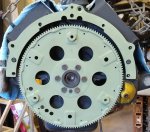
Here is the adapter in place with the drilled out hole, I did not install the extended dowel pins in the mock-up engine, but they would be installed in any actual installation, because the bolt pattern is symmetrical in this case it does not matter which way the adapter plate is applied to the block.
IMG_20210923_150657388.jpg
And here she is all bolted up with 6, 3/8x1 3/4" and 1, 3/8x1 1/4" flange head screws, I am not sure why I always call these bolts, quick lesson here, a SCREW only becomes a BOLT when a NUT is applied to the other end, if it self taps, self drills and taps or is threaded into a tapped hole it is a screw!
IMG_20210923_151436027.jpg
So there you have it the coupling between the engine and transmission is complete, now to get a 6L80 and do the installation.

OH YES I almost forgot, there are no issues with clearance between the starter nose and the the converter housing, it would however be difficult to build a completely sealed dust cover for this installation but that really is only necessary if you go fording on a regular basis and if you do I doubt the factory HMMWV dust cover really keeps out the water anyway..
IMG_20210918_094709611.jpg
OVER!!
 
Last edited:

Mogman

Moderator
Staff member
Moderator
Steel Soldiers Supporter
7,017
9,694
113
Location
Papalote, TX
I should be traveling to Houston on Oct. 8th to pick up a rebuilt 6L80
 

Mogman

Moderator
Staff member
Moderator
Steel Soldiers Supporter
7,017
9,694
113
Location
Papalote, TX
Great to see you found a solution to the problem of shavings sludge in the first transmission. I'm keeping my eye on this project.
I have a pretty good feeling about these folks even though I have not done business before, there may be a little delay as they are ordering me a custom rebuilt converter since there is no factory one available with a stall speed to match the 6.2L
 

Mogman

Moderator
Staff member
Moderator
Steel Soldiers Supporter
7,017
9,694
113
Location
Papalote, TX
Drove into Houston this morning and picked up the rebuilt 6L80 and custom low stall converter, I am working out the final details of the clocking ring and should have the transmission and transfer case coupled up this week, I am still waiting on a bunch of odds and ends like the weld in bung for the pan temp sensor and also need to do the pre swap performance tests on the helmet top.
IMG_20211011_121621229.jpg
 

Mogman

Moderator
Staff member
Moderator
Steel Soldiers Supporter
7,017
9,694
113
Location
Papalote, TX
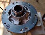
Worked out the details on the clocking ring, the clocking ring is aligned in reference to the transfer case by the 6 flat head (tapered holes) bolts, it is aligned to the factory transfer case adapter only by the 6 studs, the holes in the adapter are almost 1/2" in dia. and I originally built the clocking ring for a 700R4 it had 10MM studs, I drilled and re-tapped them for 7/16 studs but there was still much more "slop" than I could be comfortable with, I carefully aligned the clocking ring with the adapter and drilled it for three dowel pins, because of the limited "meat" available on the adapter about 3/8" wide I could only use 1/8" dowels but it will get the job done as the crush from the bolts along with some badass Loctite 638 will keep in in position.
I did manage to get those Allen head bolts torqued to 40 ft-lb, I think the factory spec is 38 ft-lb
I am not sure how others get away with just bolting them together but there are tons of clocking rings out there, I may be just be too picky...
IMG_20211014_145611791_HDR.jpg
IMG_20211014_145651550_HDR.jpg
The last of the hardware needed will be here Sat. so I can get the transfer case attached to the 6L80..

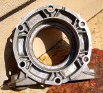
Also note the weep holes in the adapter, this is a dry coupling as the transmission has a seal in the case for the output shaft.

EDIT, oh yes I forgot, the holes in the transfer case go through to the inside of the case so I used a thread sealer/locker on them.
IMG_20211014_151558152.jpg
 
Last edited:

Mogman

Moderator
Staff member
Moderator
Steel Soldiers Supporter
7,017
9,694
113
Location
Papalote, TX
Well I got the transfer case coupled up to the transmission, possibly the first time a HMMWV transfer case has been coupled to a 6L transmission.
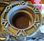
I used three kinds of Loctite on the clocking ring and the transfer case adapter, 638 on the flange face just for good measure and 272 high strength on the stud to clocking ring and 242 mid strength on the stud nuts
IMG_20211016_143221214.jpg
IMG_20211016_162037359.jpg
IMG_20211016_162047138.jpg
IMG_20211016_162110495.jpg
IMG_20211016_162124764.jpg
It is getting close to the where the real work begins!!
 

Mogman

Moderator
Staff member
Moderator
Steel Soldiers Supporter
7,017
9,694
113
Location
Papalote, TX
Took the helmet top out this morning and did some 0-60MPH runs, I aborted any run where the fan came on, I managed to get 10 runs in, tossed out the lowest and highest times and averaged out the remaining 8 runs, it came out to 27.4 sec. and the tach is registering 2900 RPM at 60MPH. all the times were pretty close and there were two that were exactly the same down to 1/100 of a second.
I am hoping these numbers will improve with the 6L transmission.
 
Top
AdBlock Detected

We get it, advertisements are annoying!

Sure, ad-blocking software does a great job at blocking ads, but it also blocks useful features of our website like our supporting vendors. Their ads help keep Steel Soldiers going. Please consider disabling your ad blockers for the site. Thanks!

I've Disabled AdBlock
No Thanks