• Steel Soldiers now has a few new forums, read more about it at: New Munitions Forums!

  • Microsoft MSN, Live, Hotmail, Outlook email users may not be receiving emails. We are working to resolve this issue. Please add support@steelsoldiers.com to your trusted contacts.

803 Bogs Down and dies at 85% Load

strycnine

Member
223
8
18
Location
Claxton, GA
with the ring installed on the piston and compressed in the groove you measure the gap from end to end. there is also a spec you use a feeler to measure the gap above or below the ring and the groove.
When I built gas engines I put the rings in the cylinder to check gap. Make sure its square in the bore when you check the gap. Check the gap at the top of the cylinder and bottom, use the tightest one to set gap. I used an upside down piston to get the rings square in the bore.
 
Last edited:

DieselAddict

Well-known member
Steel Soldiers Supporter
2,543
2,093
113
Location
Efland, NC
There are many gaps. Are you speaking of the gap in the piston for the rings (measured) (those are all .080, .070, and .156 in respectively), the gap as shown here? https://www.aa1car.com/library/ring_end_gap.htm
.......which leads to where to put the ring on the piston for measurement....
If the gap between the ring ends, then no, on my today list because I have to find the correct spot.
That is what I'm talking about. You need (as it shows in the diagram) to measure at the top and bottom of travel. Don't measure outside the area where the rings move in the cylinder. I personally do top, middle, and bottom. That also confirms the taper in the cylinder. Make sure the minimum gap you measure meets the specification. If you error be sure to error on the side that leaves more gap, not less. You don't want to break a ring if you run it hard and really put some significant heat in it.

You don't put the ring on the piston to take this measurement. You put the ring in the cylinder without the piston but use a piston facing down to set the ring at the height in the cylinder where you are going to do the measurement. The ring needs to oriented in the cylinder just like it would be on the piston for an accurate measurement. Start at the top most spot where you see ring wear and take a measurement. Push the ring down to the mid point with the piston and measure again. Finally push it down to the bottom of the ring wear area and measure one more time.
 

USAMilRet

Member
390
15
18
Location
Tampa, Florida
When I built gas engines I put the rings in the cylinder to check gap. Make sure its square in the bore when you check the gap. Check the gap at the top of the cylinder and bottom, use the tightest one to set gap. I used an upside down piston to get the rings square in the bore.
Yeah...that is how I was going to do it. But kind of a mute point as I have ordered new main bearings, center bearings, the roller bearing, thrust plates, and the rings. I already have the rod bearings on their way. Due to a PM I got today, I will be able to remove the generator motor from the cabinet so it is coming out and going all the way down do its constituent components.

I am going to do it though just to get the specs on them.

The seller (I texted this afternoon) has assured me that all the bearings are supposed to be new. He wants to see pictures of the rod bearings because he can not believe that there is copper showing after only 15 hours of use.
 

USAMilRet

Member
390
15
18
Location
Tampa, Florida
That is what I'm talking about. You need (as it shows in the diagram) to measure at the top and bottom of travel. Don't measure outside the area where the rings move in the cylinder. I personally do top, middle, and bottom. That also confirms the taper in the cylinder. Make sure the minimum gap you measure meets the specification. If you error be sure to error on the side that leaves more gap, not less. You don't want to break a ring if you run it hard and really put some significant heat in it.

You don't put the ring on the piston to take this measurement. You put the ring in the cylinder without the piston but use a piston facing down to set the ring at the height in the cylinder where you are going to do the measurement. The ring needs to oriented in the cylinder just like it would be on the piston for an accurate measurement. Start at the top most spot where you see ring wear and take a measurement. Push the ring down to the mid point with the piston and measure again. Finally push it down to the bottom of the ring wear area and measure one more time.
Will do. I am going to do that in about 20 minutes from now.
 

strycnine

Member
223
8
18
Location
Claxton, GA
Yeah...that is how I was going to do it. But kind of a mute point as I have ordered new main bearings, center bearings, the roller bearing, thrust plates, and the rings. I already have the rod bearings on their way. Due to a PM I got today, I will be able to remove the generator motor from the cabinet so it is coming out and going all the way down do its constituent components.

I am going to do it though just to get the specs on them.

The seller (I texted this afternoon) has assured me that all the bearings are supposed to be new. He wants to see pictures of the rod bearings because he can not believe that there is copper showing after only 15 hours of use.
I like where you're headed with this. You will know 100% what you have.
 

USAMilRet

Member
390
15
18
Location
Tampa, Florida
That is what I'm talking about. You need (as it shows in the diagram) to measure at the top and bottom of travel. Don't measure outside the area where the rings move in the cylinder. I personally do top, middle, and bottom. That also confirms the taper in the cylinder. Make sure the minimum gap you measure meets the specification. If you error be sure to error on the side that leaves more gap, not less. You don't want to break a ring if you run it hard and really put some significant heat in it.

You don't put the ring on the piston to take this measurement. You put the ring in the cylinder without the piston but use a piston facing down to set the ring at the height in the cylinder where you are going to do the measurement. The ring needs to oriented in the cylinder just like it would be on the piston for an accurate measurement. Start at the top most spot where you see ring wear and take a measurement. Push the ring down to the mid point with the piston and measure again. Finally push it down to the bottom of the ring wear area and measure one more time.
Here they are. This engine is showing very very minimal wear.

I checked each ring in each piston sleeve in three different positions (4 really because I wanted to see what would happen if the rings bottomed out), and these are the results. I do not have a .013 or .014 feeler gauge so I used both the .012 and .015. Anything listed as .013 or .014 is not exact but is somewhere in-between there.

Piston 1 Ring (1)(2)(3):

.012
.010
.010

ring broke

.006
.006
.006


Piston 2 Rings (1)(2)(3):

.012
.012
.012

.015
.015
.015

.012
.012
.012

Piston 3 Rings (1)(2)(3):

.017
.017
.017

.013*
.013*
.013*

.012
.012
.012

* Based on my many years of the use of these types of measuring devices, the measurement of .013in is more accurate than the measurement of .014in and this is why I call it .013in.

Piston 4 Rings (1)(2)(3):

.010
.010
.010

.014*
.014*
.014*

.010
.010
.010

* As above.

I know, you are going to say I did something wrong. I can assure you that I did not. There is NO TAPER to these sleeves.

As I indicated above though, I went ahead and bought a new set of rings for each. I am not going to cry over $104 in rings and besides, I do not like the way that the second ring on the first piston snapped in my fingers.

I am going to pull the engine from the compartment. Only way I can get to the crankshaft to check the clearances and bearings/thrust plates on the crankshaft.
 

Demoh

Member
217
26
18
Location
St Pete, FL
Due to a PM I got today, I will be able to remove the generator motor from the cabinet so it is coming out and going all the way down do its constituent components.
Replace the rotor bearing while you are at it and remove all desert sand in the bottom of the genhead. I actually posted a thread about replacing that without removing the engine but if you area already doing that then should be a lot less cursing in your future. https://www.steelsoldiers.com/showt...ear-main-seal-replaceable-without-pulling-top
I dont recall part number because its on my notepad, which ill update that post once I find the time to polish it.
 

USAMilRet

Member
390
15
18
Location
Tampa, Florida
Well, I got a msg back from the seller. He agrees that these do not look like new rod bearings do to the wear. He said he was going to speak with his rebuilder J and see what the heck was going on. He told me he was going to provide me a parts list of parts ordered for this machine.

He assured me all these were supposed to be new.
 

USAMilRet

Member
390
15
18
Location
Tampa, Florida
Replace the rotor bearing while you are at it and remove all desert sand in the bottom of the genhead. I actually posted a thread about replacing that without removing the engine but if you area already doing that then should be a lot less cursing in your future. https://www.steelsoldiers.com/showt...ear-main-seal-replaceable-without-pulling-top
I dont recall part number because its on my notepad, which ill update that post once I find the time to polish it.
I am having trouble finding a replacement rotor bearing. This should be one of the easiest finds though. I came across a freeze plug set (expansion plugs) for the LPW and they wanted $55 for the set. That is a large pill to swallow considering what they are.

I am learning that if you want parts, do not go the Onan route. If it says Onan, the price is jacked beyond belief. For three metering shims (not even enough for one metering pump - your would need about 3+ kits) they want $16.

I find that if I use the Lister Petter stock/parts numbers, I can find more of the parts at substantially less of a cost. I see things that sell for $300 branded Onan and the same item sell for $140 branded Lister Petter.

Anyways, some more work done today. I made a decision, because I have a very bad back from an injury suffered some 30 years ago, I have decided to get something to help me lift heavy items. So today, I went out and bought a Titan gantry crane rated for 2000lbs and the trolley, and then purchased an electric winch also rated for 2000lbs. I have lots of heavy equipment that I move around a lot due to space limitations (mini mill, mini lathe, Delta 10" Table Saw, Delta shop drill press, metal band cutting saw, wood band cutting saw, blah blah..... These are things that have taken me more than a lifetime to collect and I am getting too old to man handle these things. So today I bit the bullet and got the crane and it will work fine for moving these types of gen sets around for work and other things. This really has nothing to do with the genset except is was the final straw and my wife is just going to have to understand that. But she will because she knows how much I can hurt after playing around for just a short time.

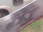
So I did some more disassembly of the housing today. Took the bearings to a friend that has owned a machine shop until recently when he retired from work, and he thinks the rod bearings are showing damage due to wear but the what caused the wear is up for debate. Based on the bearings and descriptions and pictures of the crank shaft, he thinks that there may have been oil contamination due to the scarring on the faces of the bearings He also said that given the places of increased wear, it was right at the oil feed points so there was the most contamination at those points on the bearings. He also said that they are definitely not 15 hour bearings but more like the 200 hour bearings with some slight contaminated oil. And of course due to that, it was just another reason to completely burn the house down to ashes - sort to speak - and tear the genset down completely.

I am changing my opinion of how the entire transactions was handled and to find these things out has got me quite angry about what I got from what I was told I was going to get. So we talked/texted about some other items as well.

Got the fuel stop solenoid in the mail today. I do not know just how much of the cabinet I have to take apart to get the generator and motor out as one piece, or to take the generator off of the back of the engine while the engine is still in the generator housing and once disconnected, remove just the motor and leave the generator in the cabinet, much like Demoh did when he changed the seal on the back of his genset without having to remove it from the cabinet.

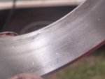
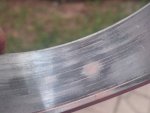
Some better shorts of the bearings. Had to wait for just the right time of day at the right angle to get these pictures to come out so well, especially when you blow the up.
20180808_200618.jpg20180808_200555.jpg20180808_200636.jpg20180808_200654.jpg20180808_200714.jpg


More parts. We have seen the roller lifters for the fuel metering pumps. They are marked to ensure they go back into the right holes. Also the backside of the governor weights that are bolted to the camshaft gear face. The fuel rack or the lever that engages the valves on the bottom of the fuel metering pumps and either turns the fuel on or off. Whether this is immediate and at a precise location on the swing, or it is a long term opening and closing like a water faucet, is not known to me and I can not test this as I do not have the equipment to generate the 3000 to 3500 psi needed to check the fuel pump or the injectors for that matter. I was able to get the fuel rack out of the compartment without taking the front of the compartment off. I did however have to remove the radiator to do it. You can just pull it out and gently nudge it this was and that way being very very very very very careful not to even put the slightest pressure on any part of this rack. About half way through the 1 and 2 (from the back of the engine) fuel metering tabs (for lack of another name) you have to get the entire rack and governor mount rotated 180 degrees (upside down) and take it out. It took me awhile to find the sweet spot and it is a very small sweet spot, but it can be done. And the oil pickup tube.
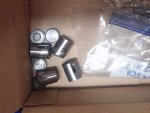
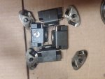
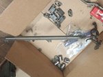
20180808_202206.jpg20180808_202214.jpg20180808_202221.jpg20180808_202229.jpg


Resolution as to what happened to some of the foam quieting material at the back (control panel) right side. Appears either a chipmunk (to small for a squirrel) or more probably a field mouse made a home.
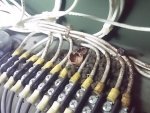
20180809_203935.jpg20180809_204018.jpg


Panel removal. Anybody can tell me what panels I have to remove or do I have to remove all of them for ease.
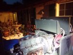
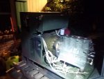
20180809_204134.jpg20180809_204145.jpg
 

Attachments

Demoh

Member
217
26
18
Location
St Pete, FL
I am having trouble finding a replacement rotor bearing. This should be one of the easiest finds though. I came across a freeze plug set (expansion plugs) for the LPW and they wanted $55 for the set. That is a large pill to swallow considering what they are.
Ill get the part number tomorrow.

Anyways, some more work done today. I made a decision, because I have a very bad back from an injury suffered some 30 years ago, I have decided to get something to help me lift heavy items. So today, I went out and bought a Titan gantry crane rated for 2000lbs and the trolley, and then purchased an electric winch also rated for 2000lbs. I have lots of heavy equipment that I move around a lot due to space limitations (mini mill, mini lathe, Delta 10" Table Saw, Delta shop drill press, metal band cutting saw, wood band cutting saw, blah blah..... These are things that have taken me more than a lifetime to collect and I am getting too old to man handle these things. So today I bit the bullet and got the crane and it will work fine for moving these types of gen sets around for work and other things. This really has nothing to do with the genset except is was the final straw and my wife is just going to have to understand that. But she will because she knows how much I can hurt after playing around for just a short time.
Sounds like I need to tour your garage/shop instead of the other way around.

Panel removal. Anybody can tell me what panels I have to remove or do I have to remove all of them for ease.
Ive removed engine and gen as one unit without removing the electronics side before, for the hassle I dont think its worth the struggle so future units I just take the front cab free from the skid. I never took the sides off like you have so I dont know if that part makes it easier.
 

Guyfang

Moderator
Staff member
Moderator
16,924
24,545
113
Location
Burgkunstadt, Germany
In theory, all you need to do is unhook the wire harness on both sides of the engine, and pull it back out of the way. If not already done, remove and pull to the side, the throttle cable. Unhook the fuel system. Unhook and remove the wires to the main generator, power and Excitor. Remove the 2 engine mounts, 2 main generator mounts and pull it out, don't mix the rubber baby buggy bumpers up. Inspect them while they are to hand. Take some silicon grease and rub them down. The engine/main gen need to be suspended, before doing the mounts. I assume the radiator is gone, so it should come right out. Since the last time I did this was 2010, there may be a few things I forgot. But it's not much. Take your time. Use at least one helper, if not two. I have done it alone, but only after doing it more then several times. And I had a wonderful 22 ton crane, that did everyplace but cook breakfast. If you don't watch out, you will smash some fingers. If you have already removed the end bell housing on the main gen, consider replacing it, as you don't need the main gen to shift on the rotor.
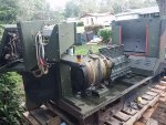
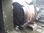
This sounds like more work then it is. CHECK EVERYTHING twice, before pulling the pack out. Look, don't assume.

510-0112 is part number for the bearing.
 

USAMilRet

Member
390
15
18
Location
Tampa, Florida
Thanks for the information. I had a lot of these things out already due to the teardown in the cabinet. So I also decided to replace a bunch of screws with SS one recommended by Daybreak so I am pretty much going to teart the cabinet apart to get to all the screws as well. Gives me something to do while I am waiting for my parts to continue on with the build/rebuild. Also gives me a chance to kind of try to bug and critter proof (like this is possible) the cabinet for Florida critters.

Very little dust or dirt in the genset so far. Do not think this unit has been out of country. Will know for sure once I start taking the generator apart to get to the rear of the engine.
 

DieselAddict

Well-known member
Steel Soldiers Supporter
2,543
2,093
113
Location
Efland, NC
I hate that you are having to go through all this BUT your work will be a boon to others that need to travel the same path.
 

Demoh

Member
217
26
18
Location
St Pete, FL
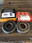
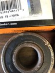
Bearing is exactly what I remembered (didn’t post in case I was wrong) it’s a 6305. RLD or 2RS, depending on what shrouding but as long as it’s a 6305 sealed both sides your should be good. (Somebody can chime in what the correct suffix is or maybe it’s brand specific)

I did get a timken 305SS but that one is mega hard to cross reference at a local bearing shop so as soon as I said 6305 the old timer there was like ‘oh yea that’s a common one’

8E50F3D9-BD17-4123-A79C-09093DC88AF4.jpgBF36E4AE-F6EA-4672-AC83-86DF786853F5.jpg

These are the ‘bad’ ones. Well they aren’t but piece of mind.
 

Guyfang

Moderator
Staff member
Moderator
16,924
24,545
113
Location
Burgkunstadt, Germany
All the army ever used was FAG. All you get here is FAG. I live 63 Klicks from the home of FAG. Got to admit, when I want a good bearing, I go for FAG.
 

USAMilRet

Member
390
15
18
Location
Tampa, Florida
Sounds like FAG is the place to be.

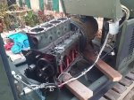
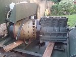
Well, I did some more teardown and the engine genset is ready to come out. I have no lift or gantry crane yet so here it sits until I get something to lift it out of the cabinet. I may just turn it some and start to remove the back of the generatror to get the the flywheel bolts while waiting for the crane (all parts are shipped and waiting arrival, including the gantry crane and electric lift). Told the wife that I have considered the crane vs a engine lift vs a jib crane, and then the gantry. As I explained the differences to her she agreed that I needed this and that I should buy it. i told her it was already on the way. Now if it was a g...

So I'll post some pictures later. Amazing thqat the only wires to be disconnected from the generator are the J5 plug and the TB3 contacts (about 15 wires - all marked 1 thru 15). Take those off and take out the two mounting bolts and the only left holding the generator to the entire set is the flywheel bolts.

Anyways, I probably took off way to much for what I needed to do but I tried to follow the TM and that was a mistake. They have not changed since the 60's 70's except there is no scantily clad lady in any of the pictures. But as a learning experience, I want to know what has to be done to do certain things like changing the crank and how much you can do with the engine in or out of the cabinet.
 

USAMilRet

Member
390
15
18
Location
Tampa, Florida
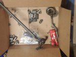
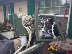
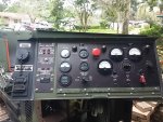
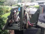
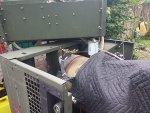
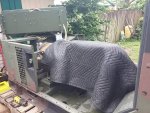
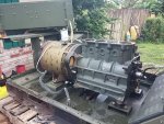
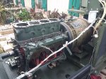
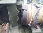
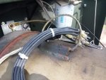
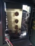
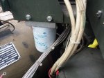
Did more work to prep for the take out of the generator and motor. I probably took off too much but the TM on disassembly references all over the place. You kno how it is, remove this by going here to do this then come back and I'll send you somewhere else to do something else them come back and we will do this again and again, blah blah blah......

So I just figured that I would take it apart as I saw fit so that I knew I could do what I had to do. now, I suspect that I will be relying on the TM when I put it back together, in great detail.

20180810_161656.jpg20180810_161702.jpg20180810_161710.jpg20180810_161733.jpg20180810_161738.jpg20180810_163150.jpg20180810_163231.jpg20180810_163313.jpg


20180810_163212.jpg20180810_163220.jpg20180810_165717.jpg20180810_165737.jpg20180810_163330.jpg


20180810_163320.jpg20180810_201018.jpg20180810_201006.jpg20180810_163346.jpg20180810_163340.jpg20180810_200004.jpg20180810_173340.jpg

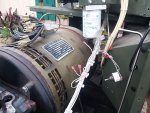
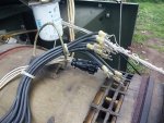
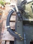
It was not as difficult as I thought it was going to be. Just be deliberate in your approach and it will all come apart relatively easy. So as far as the generator was concerned, there were 12 wires that are all marked that had to be removed at TB3 which you need to take the top lid off to get to. There is also a twist plug
J5
that needs to be disconnected that can be reached easily through the storage access door.

And got my parts today. Rings, cam bearing, main bearing, center bearings, rod bearings, thrust plates, end bearing, and of course I got the fuel solenoid earlier this week. I still have a couple items out but I have everything I need right now to rebuild this thing once I get it out of the cabinet and onto a workable surface.

I also got the rocker arm and push rod, but I am still short a head bolt and nut that was cross threaded by the rebuilder during installation.
 

Guyfang

Moderator
Staff member
Moderator
16,924
24,545
113
Location
Burgkunstadt, Germany
Did more work to prep for the take out of the generator and motor. I probably took off too much but the TM on disassembly references all over the place. You kno how it is, remove this by going here to do this then come back and I'll send you somewhere else to do something else them come back and we will do this again and again, blah blah blah......

So I just figured that I would take it apart as I saw fit so that I knew I could do what I had to do. now, I suspect that I will be relying on the TM when I put it back together, in great detail.

View attachment 737557View attachment 737558View attachment 737559View attachment 737560View attachment 737561View attachment 737562View attachment 737565View attachment 737566


View attachment 737563View attachment 737564View attachment 737571View attachment 737572View attachment 737568


View attachment 737567View attachment 737576View attachment 737575View attachment 737570View attachment 737569View attachment 737574View attachment 737573

It was not as difficult as I thought it was going to be. Just be deliberate in your approach and it will all come apart relatively easy. So as far as the generator was concerned, there were 12 wires that are all marked that had to be removed at TB3 which you need to take the top lid off to get to. There is also a twist plug
J5
that needs to be disconnected that can be reached easily through the storage access door.

And got my parts today. Rings, cam bearing, main bearing, center bearings, rod bearings, thrust plates, end bearing, and of course I got the fuel solenoid earlier this week. I still have a couple items out but I have everything I need right now to rebuild this thing once I get it out of the cabinet and onto a workable surface.

I also got the rocker arm and push rod, but I am still short a head bolt and nut that was cross threaded by the rebuilder during installation.

Oh yea, of little faith.
 
Top
AdBlock Detected

We get it, advertisements are annoying!

Sure, ad-blocking software does a great job at blocking ads, but it also blocks useful features of our website like our supporting vendors. Their ads help keep Steel Soldiers going. Please consider disabling your ad blockers for the site. Thanks!

I've Disabled AdBlock
No Thanks