• Steel Soldiers now has a few new forums, read more about it at: New Munitions Forums!

  • Microsoft MSN, Live, Hotmail, Outlook email users may not be receiving emails. We are working to resolve this issue. Please add support@steelsoldiers.com to your trusted contacts.

804B help please. False shutdowns

mciikurzroot

Active member
Supporting Vendor
153
232
43
Location
wimberley texas
Im trying to help a friend, he has 2 804B trailer mounted units, both were working well, recently one was relocated, now one of the units is experiencing what i will call false shutdowns and the set will either display an 'overspeed' or hi voltage light on the panel mount annunactor .. this shutdown is happening well before the engine even reaches operating speed or 60hz , most often as soon as the start switch is released from being in the starting position..
All suggestion or help welcomed, to circle back this set was working well and carrying full loads before being relocated..

Thank you in advance: mac/mc
 

ROTZINGER

Member
31
4
8
Location
Cancún
Im trying to help a friend, he has 2 804B trailer mounted units, both were working well, recently one was relocated, now one of the units is experiencing what i will call false shutdowns and the set will either display an 'overspeed' or hi voltage light on the panel mount annunactor .. this shutdown is happening well before the engine even reaches operating speed or 60hz , most often as soon as the start switch is released from being in the starting position..
All suggestion or help welcomed, to circle back this set was working well and carrying full loads before being relocated..

Thank you in advance: mac/mc
Not an expert by any means like other gurus here but I would suggest checking all the terminal wires to see if anything got loose in transport. Maybe follow the troubleshooting in the TMs, do you have them?

Enviado desde mi SM-G935F mediante Tapatalk
 

mciikurzroot

Active member
Supporting Vendor
153
232
43
Location
wimberley texas
Not an expert by any means like other gurus here but I would suggest checking all the terminal wires to see if anything got loose in transport. Maybe follow the troubleshooting in the TMs, do you have them?

Enviado desde mi SM-G935F mediante Tapatalk
Rotzinger, thank you for this offering or tips, these are all good suggestions and in fact i had written a near tretis on this approach probably 6 weeks ago, my pal is going to try this and i will report back on the hopeful success or what results it produces.. best: mac/mc
 

Guyfang

Moderator
Staff member
Moderator
16,923
24,546
113
Location
Burgkunstadt, Germany
The TQG's on the whole have a real problem with loose connections, and Canon plugs. Also try disconnecting the A2, and then try and start it up. But keep an eye in the volt meter, and a hand on the S7.
 

mrichard76

New member
20
3
3
Location
Louisiana
Well I opened her up, loosened and tightened all the terminals and it’s still doing the same thing. I did find out that it will run on 50hz setting although erratically swinging the frequency gauge. I also got it to run a couple times on 60 Hz while holding the switch to start but would kill when released. Most often it gives an over speed fault and occasionally a over voltage fault. It seems like the frequency pot is pretty much unresponsive while the voltage pot does modulate the voltage functionally. Mostly getting the overspeed fault when the freq needle maxes out while the engine is starting up and ramping to operating speed in a couple seconds. Engine hasn't even hit operating speed when faults and shuts down.
 

Guyfang

Moderator
Staff member
Moderator
16,923
24,546
113
Location
Burgkunstadt, Germany
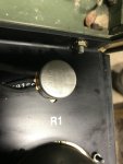
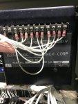
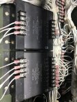
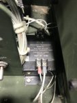
The very first thing you need to do, is check if all the parts to your volt reg system are from the same manufacturer.

Establish that your volt reg, R1, R16 and the power transformer are from Libby or TRC. One or the other. You CAN NOT MIX PARTS. Do that, and then we can go farther. But this is a must. Sadly way too many folks don't download the TM's or other information that is here in the forum. Mixing parts can damage your set. Stop fooling with the set until you can say one way or the other. When you can say you have TRC or Libby, then we can test the Volt reg, the R1 and the rest of the circuit.
 

Attachments

Guyfang

Moderator
Staff member
Moderator
16,923
24,546
113
Location
Burgkunstadt, Germany
f it were mine I would pull the voltage regulator field fuse sitting between the voltage regulator and start the following.

a. With the fuse pulled remove wire137A from terminal 5 of the A1 voltage regulator and measure resistance from that wire to terminal 7 on the reconnect board. Rotate that R1 voltage adjust from minimum to maximum and see a nice smooth resistance increase and decrease from 0 to 10 or 20 K Ohms.

b. Test that fuse ensuring it is a good one.

c. Measure resistance from the bottom of that fuse holder thru TB8 terminal 1 thru the field windings of the main gen back up to TB8 terminal 2 back up to the regulator at Terminal 3. Should be 28-38 Ohms as in the diode ring attached. This is the voltage production circuits. He gets an AC voltage as he holds the start switch in start running batt voltage thru the terminal 19 of the A5 thru the K15 and R14 thru the CR2 which is used to activate the Main gen when residual Magnetism is gone.

d. Use the color coded schematic to test the TR1 voltage sensing transformer. Should get readings as in the color coded schematic.

e. Ensure his regulator and TR1 are from the same folks as in the attached PS magazine. This and the R1 all must match. Wired correctly too hence the attached wire schematic and wiring guide.


Now before things start leave the fuse out, and check wiring of the A5 GCU. Now pull and check each ice cube relay. Use batt voltage to energize relays while testing

Make required adjustments as in the attached. Foot stomp make the three in the middle as in the attached picture. Set the speed with the freq adj in the middle, and the over speed set to about 66 hertz. If it is too tight open the window a little to 72 hertz.


Now replace the fuse, and deal with the AC Output adjusting the regulator with Volt adj in the middle. If all was good and reconnect board tight and secure ALL BETTER.
 

Attachments

Top
AdBlock Detected

We get it, advertisements are annoying!

Sure, ad-blocking software does a great job at blocking ads, but it also blocks useful features of our website like our supporting vendors. Their ads help keep Steel Soldiers going. Please consider disabling your ad blockers for the site. Thanks!

I've Disabled AdBlock
No Thanks