• Steel Soldiers now has a few new forums, read more about it at: New Munitions Forums!

  • Microsoft MSN, Live, Hotmail, Outlook email users may not be receiving emails. We are working to resolve this issue. Please add support@steelsoldiers.com to your trusted contacts.

A/C Voltage regulator board repair

Grega

Member
205
1
18
Location
St. Paul Nebraska.
I have 2 A/C regulator boards that are need of repair. The trouble with them is voltage fluxuation between 100 to 150 volts. Soldered in a new output transister on one of them but the problem still exist. Did some searching and found that Gulf Coast Military Equipment work on them. Is this correct and is there someone else that repairs them. THANKS Greg
 

derf

Member
926
13
18
Location
LA
I'd try an SX460 for $60 before I spent too much on having one repaired. I'm confident I could repair them myself. If you want original then by all means fix em. If you want functional and reliable then consider a modern VR or have them totally rebuilt with new components, at least new transistors, diodes, and capacitors.
For $60 you can have a spare on the shelf, too.
The SX460 and the Hardy Diesel $20 meter are two viable options if you don't mind non-original parts.


Isaac-1

Well-known member
1,970
48
48
Location
SW, Louisiana
Hardy diesel is a generator dealer in California, they used to do a lot of business in imported china diesels before the EPA crack down. They also sell a cheap digital volt/hz meter for about $20 on ebay ( it is not shown on their web site).

Ike
 

derf

Member
926
13
18
Location
LA
It has been noted that the Hardy Diesel meters are not easy to read in direct sunlight. But, for $20 they are in some ways better than the KillAWatt.

Isaac installed a SX460 on his 016. I've run a 016 with one but haven't made the install permanent, yet. Wiring on an 002 or 003 should be similar, I think.
 

Attachments

derf

Member
926
13
18
Location
LA
I'm not an expert but below are some of my opinions. Use them at your own risk. When/if I get around to fixing my 003 and if the VR is not working I plan to use an SX460. When/if that happens I plan to document it and share the knowledge. If you do not understand what is going on and the risks involved then you should probably just buy a good original VR and have it swapped out by a good generator tech. Sorry for the disclaimer but if you burn your stuff up please don't come crying to me. I warned you.


Looking at the 003 schematic it appears as though the original VR monitors the gen output via the current volt transformer (CUR VOLT XFMR). The SX460 is powered by and monitors either a 120V or 240V (selected by a jumper on the SX460).

If TB5 12 and 13 measure 120V or 240V during normal operation then you could probably use those for the input on the SX460. If not, the 120V at the convenience outlet should work.

Output from the SX460 would go to F1 and F2.

R1 would be external voltage fine adjustment on the panel.

What I don't know is how exactly the VR interacts with the A4 Bridge Assy. Maybe someone can enlighten me on that.


Attachments

Isaac-1

Well-known member
1,970
48
48
Location
SW, Louisiana
I have a few guesses about the MEP-002a/003a voltage regulator circuit, but have not studied it in detail, one thing that I can say is that I see no reason that an SX-460 should not work (the field resistance and current are within the spec range), it is not as plug and play as installing on a MEP-016 family generator. A few key points that may require modification of the wiring:

1, transformer noted by Derf, this may be in the circuit for ground isolation, so careful studying of the entire circuit including what happens with the voltage reconnection switch should be done before removing.

2, another grounding issue, it appears these use a grounded field design where F2 is grounded and not brought back to the voltage regulator, I have seen limited reference to using an SX-460 in this way (F2 on AVR to F2 exciter, F1 on AVR to ground, and connection point 7 on the AVR to your hot AC line, leaving 6&8 NOT connected)

3, I suspect the A4 bridge assembly is part of the voltage regulation circuit that would be handled onboard on SX-460 and should be removed from the circuit if retrofitting, this would also require more detailed look at the design. Onan uses something similar on many of their AVR's of the same time period (YD and UR series VR-21).

Ike
 

derf

Member
926
13
18
Location
LA
The 002s and 003s have motor control relays (DC control circuit) and things that are powered by what? If the answer is that bridge then we'll have to look closely at what to keep and what to remove.

The Field, being a DC thing, should not matter for grounding purposes, right? It may be tied to ground just as a convenient way to connect the negative side.

I'm sure the SX460 will do its job and excite the field and regulate the AC. The question becomes what, if any, other mods are necessary to make the 003 continue to work on the motor control side?


derf

Member
926
13
18
Location
LA
Looks like G2 (battery charge 24V alternator) may feed the motor controls.

Maybe the Bridge is just there to feed the Curr Volt Xfmr for the meters? That seems to make sense.

If so, then the Bridge gets to stay and connections are:

SX460........................................................................................Gen
1 ........................................................................................VR connector 8
2 ........................................................................................VR connector 13

3-4 jumped together

X (Field 1) .......................................................................... VR connector 12
XX (Field 2) .........................................................................VR connector 18

7 (120V feed) ................................................................J14 1 (convenience outlet)
8 (120V feed) ................................................................j14 2 (convenience outlet)

You should then be able to disconnect TB5 12 and TB513 to remove the transformers powering the VR but leave the Hz meter connected. You may be able to power the SX460 from 12 and 13 but it seems to feed through a section of the CVT1.


Last edited:

Triple Jim

Well-known member
1,373
277
83
Location
North Carolina
Maybe the Bridge is just there to feed the Curr Volt Xfmr for the meters?
The bridge rectifies the AC output of the windings of the current transformer that are connected to it, changing the AC to DC, so the bridge isn't feeding the transformer, the transformer is feeding the bridge.
 

derf

Member
926
13
18
Location
LA
OK. Why is the output of the Bridge parallel with the Field and I assume the output of the VR?
 

Triple Jim

Well-known member
1,373
277
83
Location
North Carolina
I've been sitting here wondering that too. I'm starting to think that the bridge output is what's supplying current to the exciter field, and the regulator board regulates that by passing DC from CR6 and CR7 (supplied by AC from T1) through terminals C1 and C2 of the current transformer, and back through Q3 to ground in the regulator, to saturate the iron that X1, X2, and X3 are wound on when the exciter field current needs to be reduced.

Lets hope an electronics guy who doesn't struggle with this as much as I do joins in.

From what I'm seeing so far, I think I'd repair my regulator board before I tried to substitute a different one. After all, it's an old style board with lots of real estate and large, cheap parts.
 

derf

Member
926
13
18
Location
LA
Maybe the regulator regulates by sinking the output of the Bridge?
Or, maybe the VR adds DC to supplement the Bridge output?


Triple Jim

Well-known member
1,373
277
83
Location
North Carolina
Maybe the regulator regulates by sinking the output of the Bridge?

The regulator can't sink the output of the bridge because the connection from the bridge output goes to regulator terminal 18, and that doesn't go to anything that can sink much current.

Or, maybe the VR adds DC to supplement the Bridge output?
The bridge's negative output goes to the regulator's negative bus by way of terminal 12, and its positive output goes to terminal 18, again, not capable of adding to the bridge output.

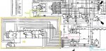
T1's output passes into the regulator board by terminals 15 and 16, and is then rectified by CR6 and CR7. This DC is sent to Q1 and Q2 in the regulator, which control T3, but it also passes directly out of the regulator by terminal 14 and into current transformer terminal C2. After passing through the three windings, and keeping in mind that this is DC, it then enters the regulator through terminal 17, and is sunk to ground as needed, through T3.

I don't see any conclusion other than the regulator controlling the exciter field by saturating that part of the transformer, which would reduce the input to the bridge. The regulator board's input signals come from the current transformer, and from T1, which is connected to the main output of the generator, so T1 provides the voltage signal to the regulator.

This means that when the output of the generator reaches too high a voltage, the regulator can control that by reducing the output of the bridge that feeds the exciter field, making a proportional feedback loop, Also, when the current requirement of the generator increases, which would cause an output voltage sag, more current is provided by the current sensing transformer to increase exciter field current to prevent the sag before it actually happens, making a sort of derivative feedback loop. The output of the bridge also gets back to the regulator through terminal 18 to R15 (or R16, depending on the version of the regulator), which is capacitively coupled to the base of Q2, so it looks like R15/R16 may control the transient response of the generator output, that is, how well it responds to sudden increases or decreases in load.

My brain hurts, I'm going to get back to work... :razz:

Edit: The technical manual has a section for adjusting R15/R16, and says to adjust it counterclockwise until the output voltage becomes unstable, then turn it clockwise until it stabilizes, then continue 2 turns. It goes on to say that instability will be most obvious following the addition or removal of a load. This confirms that R15/16 effects the ability to handle sudden load changes.

Another Edit: From tech manual:

6-3. VOLTAGE REGULATOR.
excitation current is controlled through the static type automatic voltage regulator. The voltage regulator continuously compares the output voltage of the synchronous generator with a stable reference voltage. The difference between the two voltages constitutes an error signal which indicates an output voltage that is higher or lower than the generator set point. This error signal is amplified and used to control the direct current output of the voltage regulator which is applied to the control windings of the current-voltage transformers.
This confirms that the regulator controls the generator by applying current to the current transformer.
 
Last edited:
Top
AdBlock Detected

We get it, advertisements are annoying!

Sure, ad-blocking software does a great job at blocking ads, but it also blocks useful features of our website like our supporting vendors. Their ads help keep Steel Soldiers going. Please consider disabling your ad blockers for the site. Thanks!

I've Disabled AdBlock
No Thanks