• Steel Soldiers now has a few new forums, read more about it at: New Munitions Forums!

  • Microsoft MSN, Live, Hotmail, Outlook email users may not be receiving emails. We are working to resolve this issue. Please add support@steelsoldiers.com to your trusted contacts.

Advanced Electrical Diagnostics Needed M1078

Lugnuts

Active member
Steel Soldiers Supporter
274
206
43
Location
Myakka City, FL
Yep, the LBCD(circled in red) is only on the A1 and as mentioned senses battery voltage and load and controls the load disconnect relays(circled in green) Via,the other connections/wires.

The A0 polarity protection box only has the large diodes, 4 terminals and just the 6 large cables connected to it. It also doesn't have the disconnect relays circled in green or the manual disconnect between the relays and batteries... this is a pic of an A1 schematic.
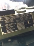
Thanks a lot/ Printing as we speak/ How do I know which is an A1 or an A0/ Production 10/97
 

Attachments

Lugnuts

Active member
Steel Soldiers Supporter
274
206
43
Location
Myakka City, FL
Yep, the LBCD(circled in red) is only on the A1 and as mentioned senses battery voltage and load and controls the load disconnect relays(circled in green) Via,the other connections/wires.

The A0 polarity protection box only has the large diodes, 4 terminals and just the 6 large cables connected to it. It also doesn't have the disconnect relays circled in green or the manual disconnect between the relays and batteries... this is a pic of an A1 schematic.
Thank you for the schematics. I don't know how to send out likes or work this site yet but you most certainly are getting an "atta boy" directly from me. Thank you
 

Lugnuts

Active member
Steel Soldiers Supporter
274
206
43
Location
Myakka City, FL
Thank you for the schematics. I don't know how to send out likes or work this site yet but you most certainly are getting an "atta boy" directly from me. Thank you
Sir, where might I obtain a set of schematics for the A0 truck/ as in all the systems/ Starting charging etc.
 

Lugnuts

Active member
Steel Soldiers Supporter
274
206
43
Location
Myakka City, FL
Gentlemen
Thank you so much for your time and knowledge. I worked on the truck today and for information the production date is 10/97/ Apparently it is an A0 model because of the descriptions that were sent as to what an A1 is/ I do need one of the boxes or the answer to who rebuilds them correctly/ I know I need one of the boxes because one of the 12vdc lugs broke. It had been heat stressed completely through and the nut was quite bonded to the stud. Tried working it off nicely, forward backward but.../ It is a MSN 19207-12420932/ The other item that would really be helpful now and in the future is a complete set of schematics for this unit/ One of you sent me a A1 Charging schematic and that was really great. Thank you/ I know I have other questions but I think the schematics would clear all that up.
Guys thank you for your time and knowledge and I'm not taking it for granted. Lugnuts
 

coachgeo

Well-known member
5,065
3,392
113
Location
North of Cincy OH
Where might I obtain a Polarity Protection Device for an A0?
you can bypass the polarity protection box. someone will pop in and follow up how to bypass properly. IMHO later when you find one... replace it. save you a headache from someone confused hooking up a jump to all those batteries and doing it wrong.

Bryce on Facebook or Suprman here and on Facebook (Will ) are two of many whom may have a box. .


all the TM's for the A0 are on this board...(see the Technical Manual ? TM forum and search LMTV) or thru the "Announcements" section of the LMTV MTV facebook group.

Found doing a quick internet search the part of TM volume / page with schematics

electrical system schematic - TM-9-2320-365-20-5_539
 
Last edited:

tennmogger

Well-known member
Steel Soldiers Supporter
1,579
538
113
Location
Greenback, TN
The electrical schematics are in the Manual TM 9-2320-365-20-3. Find this on this forum by looking in MANUALS, Present Conflict, second page from there, 8th line down,

FMTV manuals then TM 9-2320-365-20-3. The schematic pages are near the bottom of the manual, around page 1134 and down.

It will take some time to get to know how these pages work but well worth the time.

You made one statement that is key, I think, you said the truck engine keeps running after the failure. That means the fuel cutoff still has power and that could help immensely. I may have time tonight to help by looking in the manual at the schematics.

I don't have a spare Protection Box

Keep plugging at this!
 

Ronmar

Well-known member
3,418
6,856
113
Location
Port angeles wa
1997 makes yours an A0 alright... What tenmonger said, there is a complete set of A0 manuals available in the manuals section of this site which is the first section at the top of the main/home page. There is an electrical schematic in the back of every manual. If you send me an email address, I have separated out just the electrical schematic which I can email to you. I cleaned it up and reduced its file size so it is easier to use on a laptop or tablet.

Yes, you can bypass the polarity protection box, it is just a diode in the 12v and 24v pathways, designed to protect the electronics from some knucklehead hooking up batteries incorrectly. When you get the manuals in them you will find a procedure with diagrams for replacing it. To bypass you basically move the two wires on the output ports to the input ports. Or if that is where y0ur bad terminal is, move the 2 wires on each input, to their respective output. IE: the 2 wires on the 12V input bolt get moved to the 12v outlet bolt and added to the output wire already there. repeat the same for the 24v lines.

dont think these can be/were not designed to be rebuilt. There are some suppliers and scrappers here who can probably get you one...
 

Lugnuts

Active member
Steel Soldiers Supporter
274
206
43
Location
Myakka City, FL
1997 makes yours an A0 alright... What tenmonger said, there is a complete set of A0 manuals available in the manuals section of this site which is the first section at the top of the main/home page. There is an electrical schematic in the back of every manual. If you send me an email address, I have separated out just the electrical schematic which I can email to you. I cleaned it up and reduced its file size so it is easier to use on a laptop or tablet.

Yes, you can bypass the polarity protection box, it is just a diode in the 12v and 24v pathways, designed to protect the electronics from some knucklehead hooking up batteries incorrectly. When you get the manuals in them you will find a procedure with diagrams for replacing it. To bypass you basically move the two wires on the output ports to the input ports. Or if that is where y0ur bad terminal is, move the 2 wires on each input, to their respective output. IE: the 2 wires on the 12V input bolt get moved to the 12v outlet bolt and added to the output wire already there. repeat the same for the 24v lines.

dont think these can be/were not designed to be rebuilt. There are some suppliers and scrappers here who can probably get you one...
Thank you and will by-pass to see if that is actual problem.
 

Lugnuts

Active member
Steel Soldiers Supporter
274
206
43
Location
Myakka City, FL
Good Morning Gents
I downloaded TM9-2320-365-20-3 as recommended and I cannot find in the manual schematics pertaining to this unit. I did not find a listing in the content of the manual any schematics. You have the schematics andI don't therefore one would conclude that I am doing something wrong. Please advise and thank you.
 

tennmogger

Well-known member
Steel Soldiers Supporter
1,579
538
113
Location
Greenback, TN
Page 1135 is the symbols page followed by MANY pages of schematics. What are you seeing? I referred you to volume 3 so that seriesvof pages applies, but if you look in the back of other 20 series manuals you will find electrical schematic s too, as Ron pointed out.

Maybe it would help us help you if you are more specific about what you mean by "failure" specifically what continues to work (like engine running) and what stops working. Be specific.

If the engine still runs then the fuel shutoff solenoid is still powered and that comes from the PDP, via the start inhibit relay, so the PDP HAS power, etc. However, it occurs to me that someone might have made the fuel solenoid modification to power it off the alternator (mods highly complicate group troubleshooting). Where did you get your truck?
 
Last edited:

Ronmar

Well-known member
3,418
6,856
113
Location
Port angeles wa
You don't need to download one manual, you need to download ALL 9 of them. You will find electrical troubleshooting in the -1 manual, which will lead you to a specific repair in chapter 7 which is found in the -3 manual. I would not print any of them, they are thousand pages long In many cases. they are in PDF format and have embedded links, so from the index at the front of a manual you see what you are looking for, click on the listed page or paragraph number and it will automatically take you to that page in the same manual. You can also use the search function of the pdf reader... In the back of each of these manuals is a 40 page electrical, pneumatic and hydraulic schematic.

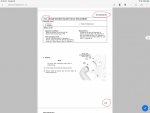
the polarity box is actually called a polarity protection relay even though it is not technically a relay... the procedure for replacing it is in chapter 7, paragraph 7-27... here is a cheat pic for you. manual#, paragraph and page number are circled in red In the attached pic. there is a class or sometimes just a few hours/days at the start of a service course to teach techs just how to use the manual. Unfortunately you don't have that and will have to learn the manuals on your own.

my advice to you is read ALL of the operators manual, and open each manual and start with the table of contents At the beginning.

7D659335-9BCD-41DB-A2E1-D8A7D21E255B.jpeg
 

coachgeo

Well-known member
5,065
3,392
113
Location
North of Cincy OH
Good Morning Gents
I downloaded TM9-2320-365-20-3 as recommended and I cannot find in the manual schematics pertaining to this unit. I did not find a listing in the content of the manual any schematics. You have the schematics andI don't therefore one would conclude that I am doing something wrong. Please advise and thank you.
yep...... like others said...... there is a lot of manuals.

Click here for >>>>>> my post earlier which pointed out the pages for schematics..... you can even roll thru them online via the link.
 

Lugnuts

Active member
Steel Soldiers Supporter
274
206
43
Location
Myakka City, FL
Page 1135 is the symbols page followed by MANY pages of schematics. What are you seeing? I referred you to volume 3 so that seriesvof pages applies, but if you look in the back of other 20 series manuals you will find electrical schematic s too, as Ron pointed out.

Maybe it would help us help you if you are more specific about what you mean by "failure" specifically what continues to work (like engine running) and what stops working. Be specific.

If the engine still runs then the fuel shutoff solenoid is still powered and that comes from the PDP, via the start inhibit relay, so the PDP HAS power, etc. However, it occurs to me that someone might have made the fuel solenoid modification to power it off the alternator (mods highly complicate group troubleshooting). Where did you get your truck?
Thank you for answering me. I went to the pages in the manual that you stated and yes it is there as you had said. I did not find it in the Table of Contents mentioned anywhere and after leafing through many pages and what I thought was going to the end of the manual, well let's just say I was wrong and you have corrected my error. Thank you
Now the "failure" is power to the transmission for one and the problem with starting is not that it loses power to the starter itself but to the solenoid activation so when you push the button you get the starter momentarily engaging and then stop then momentarily engaging and it repeating as in bump bump bump etc so it is losing constant power. Now after finding components and cleaning cables to them I think I found the problem. When working with the Polarity Protection the 24vdc side was secure but on the 12vdc side it appeared not to be loose but the stud had been hot and changed temper and the nut was bonded to the stud pretty much indicating lots of heat. The lugs themselves indicating the same. The stud twisted off even though penetrating oil and time and working were used. Now that I know that Diodes are in the box then I know that it shouldn't be an intermittent problem, it will either go or no go. I by-passed the Polarity Box and securely fastened the cleaned cables and so far it seems to be working well but being it was an intermittent problem that just started on a proven truck and now we do have brush season here in Florida and the truck is running quite frequently it should prove out pretty fast.
The truck was issued from the State of Florida through the Forestry Division but I have pretty convincing suspicions that the truck was a parts donor truck until someone threw parts on it and reinstated back to service last year.
I plan on using the schematics to see what 12vdc powers and to see what 24vdc powers and I still have the question of power distribution when I actually flip the Master Switch.
So right now I am running and will let y'all know how the story goes in a couple of weeks.
I truly appreciate the assistance of all who helped me and the "Steel Soldiers" website that I have colleagues and gear heads to go to for my mechanical consoling and parts chasing.
Lugnuts
 

NDT

Well-known member
Steel Soldiers Supporter
10,240
6,066
113
Location
Camp Wood/LC, TX
Yay! You have found the original problem that the Army never could, that caused this truck to be a hanger queen. Most certainly this problem is over. Good work!
 

NDT

Well-known member
Steel Soldiers Supporter
10,240
6,066
113
Location
Camp Wood/LC, TX
Was this really a problem for this truck?
Oh yes! The conductivity between the cables on the 12 volt diode stud would come and go with temperature humidity wetness etc. The corrosion from the heat causes the connection to become a “semiconductor” of sorts.
 

coachgeo

Well-known member
5,065
3,392
113
Location
North of Cincy OH
look for a Rev. Polarity to replace it IMHO..... it is sooo easy to accidentally jump wrong with all the batts. Might even help protect if someone throws a weld on something just a bit to close to batts and it allows for electrical charge to move thru grounds. With so much electrics..... its worth it.
 

Ronmar

Well-known member
3,418
6,856
113
Location
Port angeles wa
That pulsing when loading the circuit is a classic symptom of a bad connection. Had this about 3 days after I got my truck home from auction. It was a bad/dirty connection on the polarity box 12V terminal. It had not arced or got hot so simple cleaning fixed the issue.

When troubleshooting always measure voltage when the circuit is loaded. A bad connection will pass full voltage when there is no current flow thru the connection. when my bad connection happened, I could measure normal voltage at the 12V and 24v test points at the power distribution panel. But measuring while I pushed the start button revealed the 12V falling to 2-3V while trying to crank...
 
Top