• Steel Soldiers now has a few new forums, read more about it at: New Munitions Forums!

  • Microsoft MSN, Live, Hotmail, Outlook email users may not be receiving emails. We are working to resolve this issue. Please add support@steelsoldiers.com to your trusted contacts.

Alternate Alternator Selection

hike

—realizing each day
Steel Soldiers Supporter
538
849
93
Location
Texas Hill Country
I figured I'd post the progress here instead of the starter thread, since others may look here first for alt options.

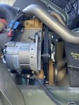
I got the delco-Remy aftermarket alt today and mocked it up with some 3/8 studs. I don't have any 4" long 3/8 bolts but I'll get them tomorrow. See photos. The unit fits perfectly in that mount with space behind. Seems peachy. My old pulley fits right on there. The shipping box had a test report in it. Says 130a max output. for $170, I'm hoping this'll be reliable. 110a is the nominal rating at 24v

The belt is obviously long. I measured a 4.5" closer pulley position from the old pulley centerline with the tensioner at half position. So that's 9" shorter belt I need.

the parts spreadsheet says the 3126 has a 78.25" long k8 belt. I wonder if Napa will have the shorter one. More research..

anyway, we'll see tomorrow if the hot test works. This delco Remy is a brush type alt and single voltage which accounts for the smaller size. Probably not as mil spec as the neihoff but I just need simplicity.
Well for 'only' 8x the cost we dropped in a Leece Neville 24v 200a unit. It required modifying the J180 bracket, though used the existing serpentine. Our intended loads add up to more amperage than yours, though I like the small form pad mount unit you have and the thriftiness. Admirable work! I am feeling like a spendthrift.

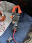
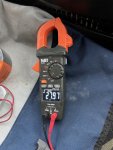
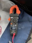
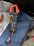
With the LBCD, battery disconnect relays removed and the Victron 24/12 70a mounted under the PDP supplying 12v to X3 we are seeing good voltage and little draw (0.05a).

Before starting at X1 and X3
IMG_4023.jpeg

IMG_4024.jpeg

After starting
IMG_4025.jpeg

IMG_4026.jpeg

We did findg a 200a alternator with a similar diameter to the Niehoff dual 100a (7" to 8"). No issue with the shock tower.
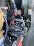
IMG_4016.jpeg

IMG_4014.jpeg

Since you also pulled your LBCD: Are you adding a voltage sensor to keep the 'Charging System' dash light operable?
 
Last edited:

cdub0451

New member
Steel Soldiers Supporter
18
21
3
Location
South Alabama
I figured I'd post the progress here instead of the starter thread, since others may look here first for alt options.

I got the delco-Remy aftermarket alt today and mocked it up with some 3/8 studs. I don't have any 4" long 3/8 bolts but I'll get them tomorrow. See photos. The unit fits perfectly in that mount with space behind. Seems peachy. My old pulley fits right on there. The shipping box had a test report in it. Says 130a max output. for $170, I'm hoping this'll be reliable. 110a is the nominal rating at 24v

The belt is obviously long. I measured a 4.5" closer pulley position from the old pulley centerline with the tensioner at half position. So that's 9" shorter belt I need.

the parts spreadsheet says the 3126 has a 78.25" long k8 belt. I wonder if Napa will have the shorter one. More research..

anyway, we'll see tomorrow if the hot test works. This delco Remy is a brush type alt and single voltage which accounts for the smaller size. Probably not as mil spec as the neihoff but I just need simplicity.
Can you provide the P/N for the alt you used, please?
 

Ronmar

Well-known member
3,881
7,549
113
Location
Port angeles wa
Here's the literature from delco. This has remote sense so is supposed to maintain 14v (28v) at battery per the info.https://www.delcoremy.com/getmedia/...elco-28SI-Single-Page-Brochure-12-14.pdf.aspx
I suspect it will run a tenth or so less than 28 at the batts(rounds to 14/28:)). Thats the beauty of remote sense, it takes the line resistance/voltage drop at the batteries when feeding current to the them, out of the equation by sensing the batt voltage on a separate line without any current flow on it… The reg on this alt will also drive a small relay or control a ignition powered dash warning light. The 28SI is on my short list for a replacement When my 100A Neihoff fails as there are a ton of them in service all over the world. With the “usa made” knockoff/compatibles ~$180, it is an inexpensive alternative, but even the genuine Delco’s are only ~$400-600

The Delco website has some cool tech assist videos. Check out the volt drop test. Probably as good a setup and description of the process to check the alt/start cables for loss as I have ever seen…
 

MatthewWBailey

Thanks for this site. My truck runs great now!
Steel Soldiers Supporter
863
1,567
93
Location
Mesa Colorado
Can you provide the P/N for the alt you used, please?
Yessir, -- Delco 28SI 24V 110 Amp 8600469 8600423 Quad Mount. Those are the aftermarket # and then the OE #. See model number sheet attached from delco. The ones I researched that have the name "Delco-Remy" on the back plastic cover are OE and typically $450+. The aftermarket knock offs are the cheaper ones. They don't have the extra name shown on the back. The seller of mine lists a 1yr warranty regardless, which is common. I saw one for a Cummins engine that had a Cummins label but it was the same delco model number for $650. So these have some variance in the price depending on whose brand name is attached.
 

Attachments

MatthewWBailey

Thanks for this site. My truck runs great now!
Steel Soldiers Supporter
863
1,567
93
Location
Mesa Colorado
Well for 'only' 8x the cost we dropped in a Leece Neville 24v 200a unit. It required modifying the J180 bracket, though used the existing serpentine. Our intended loads add up to more amperage than yours, though I like the small form pad mount unit you have and the thriftiness. Admirable work! I am feeling like a spendthrift.

With the LBCD, battery disconnect relays removed and the Victron 24/12 70a mounted under the PDP supplying 12v to X3 we are seeing good voltage and little draw (.05a).

Before starting at X1 and X3
View attachment 917640

View attachment 917639

After starting
View attachment 917638

View attachment 917637

We did findg a 200a alternator with a similar diameter to the Niehoff dual 100a (7" to 8"). No issue with the shock tower.

View attachment 917641

View attachment 917642

Since you also pulled your LBCD: Are you adding a voltage sensor to keep the 'Charging System' dash light operable?
I'll do what Ronmar mentioned above. The I-terminal can run a relay and that could trigger the existing charge system dash light. It'll have to be a reverse acting or Normally closed contact on the relay , I think since the dash light is an "alert". the alt issues the ignition light signal but my little instruction sheet doesn't say if it's on when normal or on when in alarm.
 

GeneralDisorder

Well-known member
Steel Soldiers Supporter
2,076
5,308
113
Location
Portland, OR
IDK - my experience with "Delco" in my GM travels is that once they stop using the stuff in high volume new manufacturing and for warranty and service replacements, the major (quality) manufacturers stop producing the parts and Delco will then "fill out" their catalog with Chinese crap. Lots of cheap parts inside. Voltage regulators made by relatively small low-production manufacturers in China and the quality control is abysmal. The Delco CS130's are a great example - literally NO ONE makes a decent one. Had to go to a specialty manufacturer (DC Power Engineering) to get a quality unit - and it's not a CS130. It's a newer alternator with adapter brackets and wiring harness adapter, etc. And it's $750. 🤷‍♂️

Last "Delco Professional" alternator I bought for my Trans Am lasted less than 4 months, Opened it up and they had not potted the VR's smoothing capacitor and the legs fatigued and broke off. Granted it was like $179 (wholesale, pre-pandemic) part, but I bet that cost has gone up since I tried one.

I'm sure there are quality units out there - but time will tell. If you are paying under $500 for it from a retailer..... wholesale channels (multiple levels) have to take their cut, there's shipping, and then the manufacturing. Doesn't leave much meat on that bone for quality parts. Willing to bet that production cost on a $500 alternator is under $50.
 

MatthewWBailey

Thanks for this site. My truck runs great now!
Steel Soldiers Supporter
863
1,567
93
Location
Mesa Colorado
Well for 'only' 8x the cost we dropped in a Leece Neville 24v 200a unit. It required modifying the J180 bracket, though used the existing serpentine. Our intended loads add up to more amperage than yours, though I like the small form pad mount unit you have and the thriftiness. Admirable work! I am feeling like a spendthrift.

With the LBCD, battery disconnect relays removed and the Victron 24/12 70a mounted under the PDP supplying 12v to X3 we are seeing good voltage and little draw (.05a).

Before starting at X1 and X3
View attachment 917640

View attachment 917639

After starting
View attachment 917638

View attachment 917637

We did findg a 200a alternator with a similar diameter to the Niehoff dual 100a (7" to 8"). No issue with the shock tower.

View attachment 917641

View attachment 917642

Since you also pulled your LBCD: Are you adding a voltage sensor to keep the 'Charging System' dash light operable?
Thanks. Yeah yours is pretty nice. You have way more power draw potential than mine as well with the user loads. So that's a greater requirement that justifies the cost. Every application is different so it's nice to know I can still go back to the j180 mount style with that alt you have or the common Denso 150a alt I have for my track loader, which is running $480 these days. Options are nice to have.
 

hike

—realizing each day
Steel Soldiers Supporter
538
849
93
Location
Texas Hill Country
I'll do what Ronmar mentioned above. The I-terminal can run a relay and that could trigger the existing charge system dash light. It'll have to be a reverse acting or Normally closed contact on the relay , I think since the dash light is an "alert". the alt issues the ignition light signal but my little instruction sheet doesn't say if it's on when normal or on when in alarm.
Do you have a relay in mind? We found an adjustable under/over voltage relay made for a rack mount for a protected location: ~$25 with shipping. The IP54 rated ones were all over $140, since we splurged on the alternator =/. Planning to mount next to the Victron under the PDP and use the excite circuit off K11 (thank you @Ronmar)–
 

Ronmar

Well-known member
3,881
7,549
113
Location
Port angeles wa
The delco wont require a voltage sense relay, the reg controls when it or the light is activated, so a plain simple relay(low wattage/less than 1A current draw) is all that is required. Have to look at the A1/lbcd charge light circuit, to see if it is a high side or low side control... i remember seeing it, just forget which it is:)

For the Leece, you should be able to find a basic volt sense circuit for not a lot, set to trip below say 13-13.5/26-27v to give you a charge light contact...
 

MatthewWBailey

Thanks for this site. My truck runs great now!
Steel Soldiers Supporter
863
1,567
93
Location
Mesa Colorado
The delco wont require a voltage sense relay, the reg controls when it or the light is activated, so a plain simple relay(low wattage/less than 1A current draw) is all that is required. Have to look at the A1/lbcd charge light circuit, to see if it is a high side or low side control... i remember seeing it, just forget which it is:)

For the Leece, you should be able to find a basic volt sense circuit for not a lot, set to trip below say 13-13.5/26-27v to give you a charge light contact...
Looks like load side control from Page 6, with 24v coming from lbcd when it's tripped.
 

Ronmar

Well-known member
3,881
7,549
113
Location
Port angeles wa
Uuuh thats not what I see… 2/3 of the indicator lights are looking for a path to ground to activate. The other 1/3 are looking for a voltage signal input to activate. The charge indicator, DS 27 is in the ground path indication group. Cb76 feeds power to the display which passes thru a regulator to feed one side of the indicators. The other side feeds out to the sensor contact And ground to activate. The LBCD drawing LED orientation confirms this.

if you ground LBCD connector pin B with ign power energized, that charge indicator should light. So this should be as simple as connecting LBCD pin B (wire 1853?) to that indicator terminal connection on the new alt to have it control the charge indicator directly…

here is sheet 6 of the wiring diagram showing current flow From the CB76 input on the right thru the regulator to feed 2/3 of the LEDs and the charge indicator… the LBCD connection is seen on sheet 3/15

IMG_3849.jpeg
 

MatthewWBailey

Thanks for this site. My truck runs great now!
Steel Soldiers Supporter
863
1,567
93
Location
Mesa Colorado
Uuuh thats not what I see… 2/3 of the indicator lights are looking for a path to ground to activate. The other 1/3 are looking for a voltage signal input to activate. The charge indicator, DS 27 is in the ground path indication group. Cb76 feeds power to the display which passes thru a regulator to feed one side of the indicators. The other side feeds out to the sensor contact And ground to activate. The LBCD drawing LED orientation confirms this.

if you ground LBCD connector pin B with ign power energized, that charge indicator should light. So this should be as simple as connecting LBCD pin B (wire 1853?) to that indicator terminal connection on the new alt to have it control the charge indicator directly…

here is sheet 6 of the wiring diagram showing current flow From the CB76 input on the right thru the regulator to feed 2/3 of the LEDs and the charge indicator… the LBCD connection is seen on sheet 3/15

View attachment 917786
Ok I read that backwards. I keep getting turned around on that diagram. They don't use line loops when they cross lines so it's challenging my reading glasses. I literally thought it was the reverse. Hence the need for discipline specific review! I appreciate that.
So the new alt says it can sink or source on the i terminal. So that lines up with how you suggest to connect 1853..E4379F4F-38FA-421C-93C2-DAED79C17CD5.png
 

Attachments

Ronmar

Well-known member
3,881
7,549
113
Location
Port angeles wa
Thats how i read that as well, when the alt is at proper output, that terminal can provide source to energize a relay. When it drops below set voltage, it becomes a drain, deenergizing the relay and pulling current thru the fault light...
 

Ronmar

Well-known member
3,881
7,549
113
Location
Port angeles wa
@Mathew
Ok I read that backwards. I keep getting turned around on that diagram. They don't use line loops when they cross lines so it's challenging my reading glasses. I literally thought it was the reverse. Hence the need for discipline specific review! I appreciate that.
So the new alt says it can sink or source on the i terminal. So that lines up with how you suggest to connect 1853..View attachment 917800
OK, just realized you will need to add a diode to the circuit at the alternator light connection to force it to only be a sync/path to ground, and keep it from sending power back along that line to the indicator panel when it is acting as a source...
 

MatthewWBailey

Thanks for this site. My truck runs great now!
Steel Soldiers Supporter
863
1,567
93
Location
Mesa Colorado
@Mathew


OK, just realized you will need to add a diode to the circuit at the alternator light connection to force it to only be a sync/path to ground, and keep it from sending power back along that line to the indicator panel when it is acting as a source...
So basically a diode ahead of the i terminal pointing towards the alt, so if the i terminal is not lowest voltage, no current will flow....FD4F827E-8F0A-412D-9866-312507103B34.png
 

Ronmar

Well-known member
3,881
7,549
113
Location
Port angeles wa
So basically a diode ahead of the i terminal pointing towards the alt, so if the i terminal is not lowest voltage, no current will flow....View attachment 917830
correct, you can test this by connecting the diode to the LBCD pin B and ground. if the oroentation is correct, the light will light as current flows thru the diode to ground...
 
Last edited:

MatthewWBailey

Thanks for this site. My truck runs great now!
Steel Soldiers Supporter
863
1,567
93
Location
Mesa Colorado
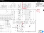
The final yard. Before powering on, I edited Page 3 of the A1 electrical Schematic for what I'm doing. Too many things for me at my age to keep track of without a drawing plus I'm supposed to be doing drawing as an EE anyway! So I'm taking my own advice. Where's the drawing? Here's a draft of the proposed changes. One's a PDF and one's a JPG. the google drive link seems to work best for resolution. I'm still advancing the art of uploading on here lol.

The red line from 1853 to Alt "i" is a wire I've added. 1851 splices to 1852. The rest of LBCD 1800 wires are open circuited. Troop heater wires were open circuited. (wear a damn coat). The little black squares are splices in the location of the deleted LBCD. I moved 1851 from the manual disco 24v load side location to the actual battery terminal for remote sensing for the alt. Note: this drawing does not show the victron chargers at the PDP, ..... yet.

oh, and a last question. 1008 to 1855 splice? or not? 1855 would drive the "battery disconnect" indicator on the A18 but only when the outside swich is activated. Not much function there but I was wondering about what to do with it. Thanks to @Ronmar for the guidance on the Alt hookup as I would've had
that backwards, leading to smoke.

Extra operator eyes on this are appreciated as I'm starting to get dsylectic, dyslectic.fmtva1electricaltm REV MWB1 2024 page-3 flat_opt_opt_001.jpg
https://drive.google.com/file/d/1G-qCnzd7UHOD2WepWtiGFCGYO6NPkpRd/view?usp=sharing
 
Last edited:

Ronmar

Well-known member
3,881
7,549
113
Location
Port angeles wa
Note: this drawing does not show the victron chargers at the PDP, ..... yet.

oh, and a last question. 1008 to 1855 splice? or not? 1855 would drive the "battery disconnect" indicator on the A18 but only when the outside swich is activated. Not much function there but I was wondering about what to do with it.
ok, so you are going to keep a standalone 12v battery and back feed 12v down the wiring from the victron to keep it charged?

IRT your last question: Are you keeping the remote disconnect relay next to the manual disconnect switch, you took it out of the drawing? The disconnect light in the dash like the charge system light, uses a path to ground to activate. That path is provided by an aux set of contacts on the disconnect relay. To drive that light from the manual disconnect switch, you would need a relay to provide that aux contact/path to ground to light the disconnect light. And with the switch open, there will be no power to run the light anyway…

IMO it is not a good idea to keep the remote disconnect relay if you are removing the LBCD. With the ability to disconnect batteries from alt while motoring, and no longer having the capacitor bank provided by the LBCD to try and catch the resulting voltage spike, I can see bad things happening when you possibly zap all the electronics with a triple digit volt peak…
 

MatthewWBailey

Thanks for this site. My truck runs great now!
Steel Soldiers Supporter
863
1,567
93
Location
Mesa Colorado
ok, so you are going to keep a standalone 12v battery and back feed 12v down the wiring from the victron to keep it charged?

IRT your last question: Are you keeping the remote disconnect relay next to the manual disconnect switch, you took it out of the drawing? The disconnect light in the dash like the charge system light, uses a path to ground to activate. That path is provided by an aux set of contacts on the disconnect relay. To drive that light from the manual disconnect switch, you would need a relay to provide that aux contact/path to ground to light the disconnect light. And with the switch open, there will be no power to run the light anyway…

IMO it is not a good idea to keep the remote disconnect relay if you are removing the LBCD. With the ability to disconnect batteries from alt while motoring, and no longer having the capacitor bank provided by the LBCD to try and catch the resulting voltage spike, I can see bad things happening when you possibly zap all the electronics with a triple digit volt peak…
Yes on the 12v battery. It seems prudent to have backup in case there's a failure of the victrons while driving.

No, I removed the relay so there's no aux contacts to run the dash light. I was just thinking there could be a test connection for the switch outside by connecting 1008 to 1855. It's of no use really, just Xmas lights. It'll just be open circuited as shown now.

Only the manual disco remains. I'm on the fence about that as well for the reasons you gave, but it is possible to lock it closed. It's a nice safety device when working in the engine comp. If it fails, contacts failure, then I'd have a possible issue but that seems low probability. Idk
454511BD-E64E-4414-8F0A-A59F7D1CE4EA.jpeg
 
Top