• Steel Soldiers now has a few new forums, read more about it at: New Munitions Forums!

  • Microsoft MSN, Live, Hotmail, Outlook email users may not be receiving emails. We are working to resolve this issue. Please add support@steelsoldiers.com to your trusted contacts.

Alternator Shorting battery

MarcusOReallyus

Well-known member
4,524
816
113
Location
Virginia
Once this is all sorted out, it's time to go back and replace the crappy "crimped with pliers" connectors. That's why a lot of people think crimp connectors are no good - they don't do it right. Use the proper tool, get good results.
 

Mullaney

Well-known member
Steel Soldiers Supporter
Supporting Vendor
7,774
19,887
113
Location
Charlotte NC
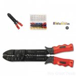
So, I have to agree with @MarcusOReallyus and his statement that "it's time to go back and replace the crappy crimped with pliers connectors" for sure. AND there are good solderless crimpers and the other ones. Pictures below. The "kit" shown below has a fairly useless crimper in that kit. It squeezes the connector a little better than plain old pliers - but not by much. The STAKE type of crimpers are "the good stuff" and is what everybody should be reaching for.


Cheap, Better than Nothing - but not by much (most likely made in china):
Cheap Stake Pliers.jpg

These are Klein Tools crimpers. The connections will stay made!
Klein.jpg

I have to relate a story about rewiring a deuce that drove the point home for me. Many years ago, wiring the truck from scratch I used a crimper like the orange (red?) handled tool. Wires kept vibrating out of the little blue solderless connectors. Things didn't work very well. Sometimes the truck would start. Other times not. Finally one of my co-workers noticed the "squeeze" connections and offered to let me borrow his pliers. New baggie of connectors and a few hours later - all those problems disappeared.

I kept those old pliers - just to remind me that cheap can cost you - dearly...

Today I have a set that looks similar to the orange ones BUT WITH STAKES (not the rounded squeeze points) like the Klein in every vehicle I own. Have to admit that I also have the Klein's as well in the shop and I reach for them first - given the chance.
 

Robtstee

New member
11
12
3
Location
Orlando, FL
Do this first. Take the wire(s) off alternator #2's negative terminal and tape them up. Run a test wire from alternator #2's negative terminal to the negative post on the rear battery. Verify the large wire connected to the positive terminal on alternator #2 goes to the rear battery positive post. Once you have the wires connected to the positive and negative terminals on alternator #2, you should see 12 volts across them.

Start the truck and see if it charges. Ignore the idiot lights on the dash and check the voltage on each battery. If it doesn't charge, do this.

Since the wiring has been changed, you will need to draw a diagram of where each wire goes and post it. It's impossible to tell from a picture of one end of the wire when the colors are different. Don't worry about the regulator wires for now. Take the big wad of electrical tape off the wire on alternator #2, you can't tell what is connected there. It looks like there are two wires on the negative terminal on alternator #2, are there? My truck only has one, where do they go? Take a picture of the batteries.
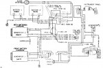
I am sure you know what you are talking about, the diagram from TM 34 E-9 looks like it has the neg. terminal is connected through a suppressor to ground (not present in my truck) and also a red wire to the engine wiring harness block. Is the diagram wrong or am I just reading it wrong? I was trying to figure out what's going on with mine. With all wires disconnected except the neg terminal I've got 12v on the neg terminal, 12v on the exciter tab, 12v on the wire to the 24v buss and 12v on the little pin. New alternator, but the situation was the same with the old one. Checked with meter and the ground is isolated from the case. Any guidance would be appreciated.
 

Tow4

Well-known member
Steel Soldiers Supporter
2,097
647
113
Location
Orlando, FL
I am sure you know what you are talking about, the diagram from TM 34 E-9 looks like it has the neg. terminal is connected through a suppressor to ground (not present in my truck) and also a red wire to the engine wiring harness block. Is the diagram wrong or am I just reading it wrong? I was trying to figure out what's going on with mine. With all wires disconnected except the neg terminal I've got 12v on the neg terminal, 12v on the exciter tab, 12v on the wire to the 24v buss and 12v on the little pin. New alternator, but the situation was the same with the old one. Checked with meter and the ground is isolated from the case. Any guidance would be appreciated.
I suggest you start your own thread to deal with your specific problem.
 
Top
AdBlock Detected

We get it, advertisements are annoying!

Sure, ad-blocking software does a great job at blocking ads, but it also blocks useful features of our website like our supporting vendors. Their ads help keep Steel Soldiers going. Please consider disabling your ad blockers for the site. Thanks!

I've Disabled AdBlock
No Thanks