• Steel Soldiers now has a few new forums, read more about it at: New Munitions Forums!

  • Microsoft MSN, Live, Hotmail, Outlook email users may not be receiving emails. We are working to resolve this issue. Please add support@steelsoldiers.com to your trusted contacts.


Alternator Upgrade Question with A Twist

jonesal

Mission Specialist
Steel Soldiers Supporter
413
68
28
Location
Brookings, SD
Forum,

I have the following battery setup on my M923:

IMG_4349.JPG IMG_4350.JPG

and am upgrading from this stock 60 amp alternator:

IMG_20220731_151455422.jpg

to this alternator that is 260 amps at 28v and 140 amps at 14v:

IMG_20220731_151501309.jpg

The reason being is that I have added an A/C kit for a M915A2 that is 14/28v, an Eyecon light system, and other electrical stuff. The wires from the alternator upgrade have to go straight to the battery banks.

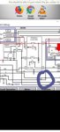
I have all my mounts, wire sizes and fuses figured out. My question is this: if I'm reading the wiring diagram correctly, I can delete wire 5 from the stock alternator to the Protective Control Box (PCB) and the stock starter system that includes the PCB will function as intended; true or false? I've ran the "simulations" on P2P and it appears so. However, all you are much more clever than me and P2P, so I'm throwing this out to you for comment.

Sorry if this belongs under the 5 ton modifications forum. Perhaps a moderator can move it if this is a violation.

Thank you,
Al Jones
Brookings, SD

PS, BTW, I've been meaning to post how the Eyecon mounted on my M923, here are a few pics; I'll post the complete install thread at a later date:


279.jpg 281.jpg


306.jpg 307.jpg
 

simp5782

Feo, Fuerte y Formal
Supporting Vendor
12,095
9,260
113
Location
Mason, TN
Wire 5 is your exciter wire. Which your alternator has to have to turn it on i believe.

Those neihoffs aren't just single wire units that put out power no matter what.

I think they are junk. I just run a 110amp 24v brushless alternator and a 24 to 12v equalizers that can handle 100amps each

It is more than enough power for the eyecon and ac kit.

The neihoffs don't put out much voltage at idle.

.
 

jonesal

Mission Specialist
Steel Soldiers Supporter
413
68
28
Location
Brookings, SD
Here are the tags on the wires from the harness. Wire "5" is the main output (with an extra "POS" tag that was on it) and the exciter wire as you call it is labelled 568 which both match the wiring diagram, P2P and tracing the wires through the harness.

IMG_20220731_185201168.jpg IMG_20220731_185138928_HDR.jpg

So not sure what you're talking about above. As far as not much voltage at output, I've also attached the load characteristics of the N1224 relative to the alternator rpms, which of course is related to the size of pully on it. The loading curves I'm seeing shows pretty decent output at idle.

N1224 Characteristics.pdf

As far as "junk", I guess I'll deal with that when and/or if it happens. I've been through the unit and am comfortable it's up to the task. I'm just trying to have fun here and seek some knowledge along the way.

Back to the main question, if anyone has any comments on eliminating wire "5", I'm all ears.

Thanks,
Al Jones
Brookings, SD
 

Attachments

KN6KXR

Well-known member
213
529
93
Location
Felton, CA
"My question is this: if I'm reading the wiring diagram correctly, I can delete wire 5 from the stock alternator to the Protective Control Box (PCB) and the stock starter system that includes the PCB will function as intended; true or false?"

The way I'm looking at it the schematic shows me power is coming out of the PCB (on wire 5 at terminal D) and feeding both 5/568/5D/5A which appear to be the alternator output and voltage target sense line. Also appears to be the charge line to the battery. There's a zener diode on the schematic in the PCB connected that looks like it prevents overvoltage.

Maybe I have the wrong schematic? You could give it a try but I would be ready to put it back. Don't tear it out of there. Like I said maybe I'm looking at the wrong schematic or I dont understand the question.
1659326770230.png
 

jonesal

Mission Specialist
Steel Soldiers Supporter
413
68
28
Location
Brookings, SD
Thanks for the helpful responses. I've also pulled the harness from the PCB and will see how wire 5 intertwines with the other wires mentioned. I like the PCB (again, I'm having fun here) so I want to keep it.

I'll post pics of the bracket I made once it's all up and running.

Thanks again!!
Allen
 
Top
AdBlock Detected

We get it, advertisements are annoying!

Sure, ad-blocking software does a great job at blocking ads, but it also blocks useful features of our website like our supporting vendors. Their ads help keep Steel Soldiers going. Please consider disabling your ad blockers for the site. Thanks!

I've Disabled AdBlock
No Thanks