Jimc this will be a great improvement to standard gauges. I'm not familiar with abs plastic and do you know the life expectancy in outside conditions. I'm just wondering if the plastic will start cracking or breaking down after 5yrs, 10yrs, 30yrs or never?
-
Steel Soldiers now has a few new forums, read more about it at: New Munitions Forums!
ammeter frequency and voltage gauges
- Thread starter Jimc
- Start date

- Status
- Not open for further replies.
More options
Who Replied?Jimc
Member
- 726
- 9
- 18
- Location
- Mullica, nj
Abs should last years and years outside. The only piece exposed to the weather and UV is the bezel. You should see no cracking. To give you an idea, the septic vent pipe on your house going out the roof is usually abs. That has to handle all the weather and the baking sun and heat all year long for the life of the house.
- 2,943
- 7,169
- 113
- Location
- West greenwich/RI
Excellent work Jimc, they look great! Too bad they weren't available a few months ago, I would have went with yours instead of the Hardy Diesel one I ended up with when one of my Hz transducers went haywire. Most likely I will still be interested in getting some gages from you, since they are so nicely done and some of my Ammeters seem to read differently than others under the same load. What would really be cool ( but apparently not an available option ) is if the gage manufacturer offered both Hz/amp and volt/amp gages, then you could have just 2 gages and monitor amps on both legs as well as Hz and volts....
Anyway...Great job!
Anyway...Great job!
Knuckles
Member
- 51
- 7
- 8
- Location
- Marshall, VA
Jimc,
wondering how you're coming on the ac voltmeter. Just picked up an 803a with a bad voltmeter ( paint has peeled and is blocking the needle). I would be very interested in one of your digital gauges as a replacement. I ordered a couple of replacements from e-bay to try out, but they look very cheap.
wondering how you're coming on the ac voltmeter. Just picked up an 803a with a bad voltmeter ( paint has peeled and is blocking the needle). I would be very interested in one of your digital gauges as a replacement. I ordered a couple of replacements from e-bay to try out, but they look very cheap.
Jimc
Member
- 726
- 9
- 18
- Location
- Mullica, nj
Yeah actually they have been done and ready for a week now. I can take orders on them but i havent formally put them up for sale because i wanted to install a set in my 003 and make an instruction sheet for them. I have just been busy. If you can do without instructions then i can ship right away. I have them made and ready to go. Just send me a pm
easttnemc
New member
- 27
- 0
- 1
- Location
- East Tennessee
I am interested....but better wait for the instruction sheet to be completed.
- 9,582
- 228
- 63
- Location
- Dickson,TN
Be sure to list them in the classifieds when they are ready for sale. If this thread turns into a for sale thread we will have to lock it.
Jimc
Member
- 726
- 9
- 18
- Location
- Mullica, nj
yeah i was borderline with those gov ends i had. it started getting bad and i knew the mods would only look the other way for so long. i will put them up there soon. i just gotta find the time one of these evenings to get the gen in the shop to do the install. in the meantime i did make a change to the box part of it where a small stainless nut is set into the plastic for the mounting screws to thread into. this way they arent threading directly into the plastic.
metalworker393
Member
- 182
- 24
- 18
- Location
- Jackson NJ
Hello Jim, please PM me when you are ready to put the add up on the classifieds as I have an 002 with a broken frequency meter. Like your set up, looks like the bezel ring is made on a vmc. Thanks metalworker393
Jimc
Member
- 726
- 9
- 18
- Location
- Mullica, nj
sure thing. all the plastic components are 3d printed
robkiller
Member
- 206
- 2
- 18
- Location
- Colorado Springs CO
Keep us posted. Pm me when listed on classified.
Jimc
Member
- 726
- 9
- 18
- Location
- Mullica, nj
ok well i got the install done and wired up for the most part. its too late for me to fire it up tonight. ill go ahead and hopefully do that tomorrow. ill get some pics with it running. ill go ahead and start writing the instructions up tomorrow evening. these are really not hard to hook up and with the one gauge being a combo volt/amp gauge it makes the installation very versatile. the instructions are just a guide really but i do want to include them so anyone can just do the install step by step.


steelandcanvas
Well-known member
- 6,187
- 88
- 48
- Location
- Southwestern Idaho
Those look superb Jim!
Jimc
Member
- 726
- 9
- 18
- Location
- Mullica, nj
thanks! i've really put alot of time into these to make them right. they have gone through change after change to keep improving on the design.
3dAngus
Well-known member
- 4,719
- 102
- 63
- Location
- Perry, Ga.
So where's the classified ad?.
What is the problem with installation. I would have thought you just take the wires off one and put on the other.
No? Probably something about combining the voltage and current meter maybe?
What about the freq meter. Is it ready to go?
Can you tell we're getting anxious? Still waiting to see if you were able to hold the line on the price.
Fantastic work. You're a real asset to SS.
Jimc
Member
- 726
- 9
- 18
- Location
- Mullica, nj
well easy but not quite that easy. you have to remember the original hz meter uses an external transducer mounted on the back wall of the control cabinet. the new gauge is all built in. you need to bring those AC wires from the back wall of the cabinet over to the new gauge. thats it really. voltage gauge wires are basically take off and put on. the current meter has pickup coils/sending unit to send the signal to the gauge. that goes in your power dist box on L1 or L3. basically remove the wire on the bottom of the main lug, slide the coil on the wire and put the wire back on. i have it all worked out on how to run the wires. its very easy. ill do the instructions as a downloadable pdf because ill include a ton of pictures to follow. for price i can keep the $45 target on the frequency meter. the volt/amp gauge will be 5 bucks more. ill make the classified ad as soon as i have the instructions all done. give me 2 more days to wrap it up.
Isaac-1
Well-known member
- 1,970
- 51
- 48
- Location
- SW, Louisiana
On the frequency meter, it seems to me the easy way would be to splice the input and output wires from the transducer together and then just move the wires from the old frequency gauge to the new one.
Ike
p.s. you probably also need to do something about shunting the original wires on the output from the amp/volt selector knob, I have read that wires through CT's should not be left open or they build high voltage, etc.
Ike
p.s. you probably also need to do something about shunting the original wires on the output from the amp/volt selector knob, I have read that wires through CT's should not be left open or they build high voltage, etc.
Last edited:
Jimc
Member
- 726
- 9
- 18
- Location
- Mullica, nj
ike glad you mentioned that. that does ring a bell and i forgot all about it.
for the hz meter that was one of my options but would end up with 2 connections. one at the gauge and the one up by the transducer. i decided to just make the wires on the gauge long enough to just run up to the ac input wires where the transducer is. atleast that way you have plenty of wire and you can hookup however you like.
for the hz meter that was one of my options but would end up with 2 connections. one at the gauge and the one up by the transducer. i decided to just make the wires on the gauge long enough to just run up to the ac input wires where the transducer is. atleast that way you have plenty of wire and you can hookup however you like.
Jimc
Member
- 726
- 9
- 18
- Location
- Mullica, nj
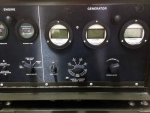
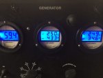
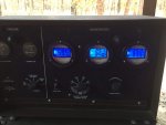
ok guys i ran her today. gauges are super and work perfectly. here are a couple pictures. ill work on the instructions tonight and tomorrow then they will be ready to go. i have my ammeters hooked up to monitor L1 and L3 which is what most of us would use on a 1ph 240v setup for our houses. if using just one gauge you can monitor L3 by itself since that carries line voltage on all but one of the voltage settings.just a note also. in person the gauges are very evenly lit. for some reason the light was screwing with my camera making the blue light look funny.
concerning what ike said about the shunt and disconnecting the wires from the original ammeter and leaving them. while my gen was running at different loads today i checked voltage on those 2 wires to see if it built up and got really high. pulling 14 amps on each leg i saw voltage on the wires reading only 15 volts. while pulling 50 amps on each leg the highest i saw was 90 volts. now the voltage as soon as i touched the wire was at 90 then after a second it would drop down to about 40-45. so you can see it does build up but i really wouldn't consider 90 volts on a wire to be extremely high. if anyone wants to give an opinion on this please feel free.


concerning what ike said about the shunt and disconnecting the wires from the original ammeter and leaving them. while my gen was running at different loads today i checked voltage on those 2 wires to see if it built up and got really high. pulling 14 amps on each leg i saw voltage on the wires reading only 15 volts. while pulling 50 amps on each leg the highest i saw was 90 volts. now the voltage as soon as i touched the wire was at 90 then after a second it would drop down to about 40-45. so you can see it does build up but i really wouldn't consider 90 volts on a wire to be extremely high. if anyone wants to give an opinion on this please feel free.


- Status
- Not open for further replies.
- 114,281members
- 167,185threads
- 2,353,710posts
- 3,697online users

