JAG
New member
- 12
- 2
- 3
- Location
- Mount Juliet/TN
Looking to create a arduino setup that reads analog inputs such as:
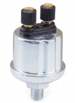
Oil Pressure
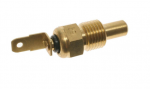
Coolant Temp
Fuel Level
etc
Displaying them on a TFT LCD screen
Instead of putting in some VDO sending units, I was thinking of using the STE/ICE port, since all signal wires are going to it.
I looked through the TM-9-6625-2301-10 and I cannot find any wiring diagram / pin output. Was hoping to not have to do a deep dive with the multimeter.
Came across this thread where they set up and used the Diagnostic Kit - which is converting the analog signal to digital. I don't see why i couldn't install a mini computer to do the same thing.
Any thoughts on how to find the pin outputs and thoughts on a digital gauges display through an LCD dashboard ?
Oil Pressure
Coolant Temp
Fuel Level
etc
Displaying them on a TFT LCD screen
Instead of putting in some VDO sending units, I was thinking of using the STE/ICE port, since all signal wires are going to it.
I looked through the TM-9-6625-2301-10 and I cannot find any wiring diagram / pin output. Was hoping to not have to do a deep dive with the multimeter.
Came across this thread where they set up and used the Diagnostic Kit - which is converting the analog signal to digital. I don't see why i couldn't install a mini computer to do the same thing.
MSD-ICE Kit Diagnostics
People sell these disks, that’s what it depends on. Benjamin People may sell them, but that's theft. These are copyrighted materials.
www.steelsoldiers.com
Any thoughts on how to find the pin outputs and thoughts on a digital gauges display through an LCD dashboard ?