• Steel Soldiers now has a few new forums, read more about it at: New Munitions Forums!

  • Microsoft MSN, Live, Hotmail, Outlook email users may not be receiving emails. We are working to resolve this issue. Please add support@steelsoldiers.com to your trusted contacts.

Another MEP-802A problem child

ufc702

New member
14
0
0
Location
Wahiawa, HI.
Hello everyone, I'm the new guy that's hoping to get some help

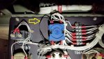
After downloading, reading, testing, reconnecting a disconnected aux fuel pump 2-wire harness, installing new oil filter, filling up with 15w40 diesel oil, new fuel filter, filling up with fresh diesel, filling with coolant, and brand new optima yellowtop 51R batteries. I am unable to find why the master switch does not do anything other than activate the "Preheat", I do hear the fuel pump activate in the "Prime & Run Aux fuel" position, "Prime & Run" does nothing new, and "Start" does nothing. Only the Dead Crank switch turns the engine over, when switched to normal, nothing at on Start position on S-1

I need to replace the fuel lines that wrap around and go to where the fuel tank is but should that prevent the "Start" on S-1 not to activate? I've been at this off and on for 3 weeks reading posts on here with people that had similar issues but I've checked as many areas that I could. It seems like a simple fix or am I just missing something? Also when I flip the panel lights to ON no power gets to the switch or the lights.
IMG_9162.jpgIMG_0044.jpgIMG_0045.jpgIMG_0047.jpgIMG_0046.jpg

2011 MEP-802A
130 hours
Nothing added to diesel

The unit is really clean looks like it's brand new, like I said I did some testing with my Fluke 1587 meter
 

robertsears1

Active member
255
119
43
Location
Near Apex/NC
When I got my 804A, it had only 46 hours. Much like you, it would not turn the engine over in start. Mine would also turn over using the dead crank switch. I started tapping on things including the starting solenoid (not sure about an 802) and eventually began to get some clicks at start. Eventually, it cranked. Also check that the red button is in the correct place. Guyfang is the generator Yoda and he will probably be along in the middle of our night (he lives in Germany). Good on you for gathering info first.

Robert
 
Last edited:

Daybreak

2 Star Admiral
Steel Soldiers Supporter
1,522
760
113
Location
Va
Howdy,
Sounds simple, but...
Push in the big emergency stop button, and then pull it back out.

update, after re-reading what you posted. It looks like the unit had the S-1 replaced. You might be better off undoing the wires and re-checking where they should go. Are the machine screws holding it on not black counter sunk machine screws?

OK, you said you had to get into the unit and do stuff with the aux fuel pump? why?
 
Last edited:

ufc702

New member
14
0
0
Location
Wahiawa, HI.
When I opened up the back panel I noticed that the harness was not connected all the way so I just corrected it and now the fuel pump turns on, I think the last person that worked on it did this because the fuel lines were leaking which I just replaced. As for S-1 the screws are silver not like the ones you described, so I will see where they were connected to.

Thanks!
 

Daybreak

2 Star Admiral
Steel Soldiers Supporter
1,522
760
113
Location
Va
Howdy,
I have one unit which has the plastic blue S-1 switch.
MEP802A panel face.jpgS-1 switch back 1.jpg
Your S-1 connections look a little off. That is why I suggest tracing out the wires for the S-1.

Fuel lines? or fuel return lines?

OH, by the way, Great first post with info which someone can help with. Has all the good info which gets us some idea which way to go. :)
 
Last edited:

ufc702

New member
14
0
0
Location
Wahiawa, HI.
Howdy,
I have one unit which has the plastic blue S-1 switch.

Your S-1 connections look a little off. That is why I suggest tracing out the wires for the S-1.

Fuel lines? or fuel return lines?

OH, by the way, Great first post with info which someone can help with. Has all the good info which gets us some idea which way to go. :)
Thanks I try to be as thorough as possible just to try and speed up the process, my mistake it's the return lines that were leaking.

My S-1 switch looks similar to yours except my S6 is like a skyscraper, almost bumped into it a few times looking inside for loose connections. I hope I can get this fixed in the next 2 days or it will be on the back burner for a few since on post housing has tiny one car garages I don't have space for it here so it has to go back to my shop and usually only have about an hour to work on it before having to get to work.

Also glad to have this on wheels so I can move it around the shop and get it on the liftgate for transport, it helps a lot.

Sunny
 

Attachments

ufc702

New member
14
0
0
Location
Wahiawa, HI.
When I got my 804A, it had only 46 hours. Much like you, it would not turn the engine over in start. Mine would also turn over using the dead crank switch. I started tapping on things including the starting solenoid (not sure about an 802) and eventually began to get some clicks at start. Eventually, it cranked. Also check that the red button is in the correct place. Guyfang is the generator Yoda and he will probably be along in the middle of our night (he lives in Germany). Good on you for gathering info first.

Robert
I tried the banging method many times to no avail I'm looking into checking if S-1 was wired correctly and then I'll bang my head a little to stay awake long enough to see if that helps me think of what could be wrong.
 

ufc702

New member
14
0
0
Location
Wahiawa, HI.
Not sure why I tested (A & B) the starter per "TM 9-2815-252-24" since the dead crank basically cranks the engine over. Did it anyways just to make sure I didn't miss anything, back to deciphering the schematics until my energy drink buzz wears off.

I have one unit which has the plastic blue S-1 switch.
View attachment 637747View attachment 637764
Your S-1 connections look a little off. That is why I suggest tracing out the wires for the S-1.

Fuel lines? or fuel return lines?

OH, by the way, Great first post with info which someone can help with. Has all the good info which gets us some idea which way to go. :)


Hey Mike I just noticed a black wire you have jumped on your S-1, mine doesn't have that. Am I missing that????


Attachments

Last edited:

Guyfang

Moderator
Staff member
Moderator
16,254
23,030
113
Location
Burgkunstadt, Germany
Check that the wires on the S-1 are right. That the diode is in right. Then with the S-1 in the start switch, you should have 24 volts on pin 7. That's the wire that will do the starting.

S-10, dead crank is only to turn over the engine, so thats good that it does infact turn over the engine. This should not be a tough problem. Let us know what you measure at pin 7. The wire diagrams on the doors will show a hook up for the S-1.

The "Black wire" is a diode. Yes, its needed.
 

ufc702

New member
14
0
0
Location
Wahiawa, HI.
Check that the wires on the S-1 are right. That the diode is in right. Then with the S-1 in the start switch, you should have 24 volts on pin 7. That's the wire that will do the starting.

S-10, dead crank is only to turn over the engine, so thats good that it does infact turn over the engine. This should not be a tough problem. Let us know what you measure at pin 7. The wire diagrams on the doors will show a hook up for the S-1.

The "Black wire" is a diode. Yes, its needed.
This is what I got, wanted to post this before I go check out the wire diagrams on the doors. Thanks for chiming in on my thread Guyfang

In the off position:

7 - 0.00
5 - 0.005
3 - 0.00
1 - 0.00
9 - 0.021
8 - 0.021
2 - 24.17
4 - 24.17

Clicking to start position
7 - 0.011
5 - 0.023
3 - 23.32
1 - 0.013
9 - 0.046 @ Prime & Run Aux fuel then 0.011 when turned to start
8 - 0.046 @ Prime & Run Aux fuel then 0.011 when turned to start
2 - 23.30
4 - 23.30

No diode on S1 itself, would it be located in a different area?
 

Daybreak

2 Star Admiral
Steel Soldiers Supporter
1,522
760
113
Location
Va
Howdy,
I can only say, that by seeing the screws holding in the S-1, it tells me it was swapped out.
 
Last edited:

Guyfang

Moderator
Staff member
Moderator
16,254
23,030
113
Location
Burgkunstadt, Germany
Pins 2,4,6 and 8 are common. Meaning they should have 24 volts on them at all times.

In the preheat position, pin 1 is connected to the common wires, to run the preheat function. So you should have 24 volts there.

In the off position, no pins should be connected to the common wires.

In the prime and run aux fuel position, pins 3 and 5 should be connected to the common wires, to run the Aux prime and run functions. So they should have 24 volts on them.

In the prime and run position, only pin 3 will be connected to the common wires. It should have 24 volts on it.

In the start position, pins 3 and 7 will be connected to the common wires. Pin 3 for the run functions, and pin 7 for the start function. Those two pins should have 24 volts.

Sooooooooooooooooooooooooooooooooooooo, according to your measurements, in the start position, you have no voltage on the pin 7. Hence no engagement of the starter. You also do not have any information about pin 6. I do see pin 9, but don't think there is a pin 9, so maybe you read the pin positions upside down.

In any case, the very first thing I would do is take all the wires off the S-1 switch. THEN, look at the wire diagram/schematic, and find the proper position, for the proper wire. The wires have numbers, the pins have numbers. Hook them up right, and then check it twice, (don't laugh, I am very serious). Then you need to get a diode and put a connector on both ends of it. Look at the wire diagram/schematic, to see in which direction the diode should be hooked up, and connect it. THEN look at your wire diagram/schematic, for the S-1 circuit schedule. It gives you the same info I gave you above, and you can then measure the switch IAW, (In Accordance With) the circuit schedule. I think you are going to find one, (or more) of the following problems. The S-1 is:

1. Hooked up wrong
2. Missing the diode
3. Possibly the wrong switch
4. Bad switch

Like Mike observed, it looks like the S-1 switch has been changed. So any or all of the above mentioned could be the problem. The missing diode is a IN5406 diode. Should be easy to get. Cost a few pennies to make, not sure what it will cost you, but I don't think you need to rob a bank. The NSN for the diode is; 5961-00-295-5757. Take a look REAL close in the control cabinet. Who knows, you might find it in there someplace. DO NOT, repeat, do not, forget to put some heat shrink, or some insulation from another wire on the diode ends, BEFORE crimping wire connectors on the ends. The TM 9-6115-641-24P shows you how to do it, with a very bad diagram. Do not cut off any of the wire ends, of the diode. Its much easier to hook it up to pins 1 and 7 of the S-1, if the wires are longer. The polarity of the diode is important, so pay attention to the schematic.

Miswiring of the S-1 was one of the biggest problems I ever saw. I kept a small paper in my wallet with the pin and wire numbers to the S-1 switch.
 
Last edited:

ufc702

New member
14
0
0
Location
Wahiawa, HI.
Wow, great information guys! I've been on a few forums and this is by far most helpful. Although I haven't solved the problem yet at least I have leads on where I should be looking in terms of getting this thing going. Going out to RadioShack to pick up a diode I saw today but wasn't sure if it was the right one, I'll post my results after I rewire S-1 and splice in the diode.
 

ufc702

New member
14
0
0
Location
Wahiawa, HI.
"Pins 2,4,6 and 8 are common. Meaning they should have 24 volts on them at all times."

In the preheat position, pin 1 is connected to the common wires, to run the preheat function. So you should have 24 volts there.

In the off position, no pins should be connected to the common wires.

In the prime and run aux fuel position, pins 3 and 5 should be connected to the common wires, to run the Aux prime and run functions. So they should have 24 volts on them.

In the prime and run position, only pin 3 will be connected to the common wires. It should have 24 volts on it.

In the start position, pins 3 and 7 will be connected to the common wires. Pin 3 for the run functions, and pin 7 for the start function. Those two pins should have 24 volts.

Sooooooooooooooooooooooooooooooooooooo, according to your measurements, in the start position, "you have no voltage on the pin 7". Hence no engagement of the starter. You also do not have any information about pin 6. I do see pin 9, but don't think there is a pin 9, so maybe you read the pin positions upside down. (Yes I was reading upside down, Ha!)

In any case, the very first thing I would do is "take all the wires off the S-1 switch. THEN, look at the wire diagram/schematic, and find the proper position, for the proper wire. The wires have numbers, the pins have numbers. Hook them up right, and then check it twice, (don't laugh, I am very serious). Then you need to get a diode and put a connector on both ends of it. Look at the wire diagram/schematic, to see in which direction the diode should be hooked up, and connect it." THEN look at your wire diagram/schematic, for the S-1 circuit schedule. It gives you the same info I gave you above, and you can then measure the switch IAW, (In Accordance With) the circuit schedule. I think you are going to find one, (or more) of the following problems. The S-1 is:

1. Hooked up wrong
2. Missing the diode
3. Possibly the wrong switch
4. Bad switch
(5. Missing jumper from 4 to 8 )

Like Mike observed, it looks like the "S-1 switch has been changed". So any or all of the above mentioned could be the problem. The missing diode is a "IN5406 diode" Should be easy to get. Cost a few pennies to make, not sure what it will cost you, but I don't think you need to rob a bank. The NSN for the diode is; 5961-00-295-5757. Take a look REAL close in the control cabinet. Who knows, you might find it in there someplace. DO NOT, repeat, do not, forget to put some heat shrink, or some insulation from another wire on the diode ends, BEFORE crimping wire connectors on the ends. The TM 9-6115-641-24P shows you how to do it, with a very bad diagram. Do not cut off any of the wire ends, of the diode. Its much easier to hook it up to pins 1 and 7 of the S-1, if the wires are longer. The polarity of the diode is important, so pay attention to the schematic.

"Miswiring of the S-1 was one of the biggest problems" I ever saw. I kept a small paper in my wallet with the pin and wire numbers to the S-1 switch.
So based on the clues that you gave I corrected the problems, who ever installed the new Master Switch didn't attach the additional parts needed to get power to the needed areas. Luckily Radio Shack came through with the diode (RadioShack PN 276-1143), I just googled "IN5406" and it showed they carried them. After I made the diode I disconnected all of the leads and checked the numbers on the wires against the schematics on the doors per your instructions and proceeded to reconnect while double checking along the way to what goes where along with the diode and still got nothing.

I was so frustrated that I disconnected all of the leads again and removed the Master Switch so that I could take it a part to see if I could figure out what the problem was. I saw a few threads where you talk about rebuilding them so I was thinking I could attempt to try to clean mine out. While sitting at the computer about to take it a part I did a quick search for replacement S-1 units and I came across one of Mike's for sale threads, clicked on his S-1 switch and viola I saw another piece of the puzzle that wasn't on my S-1. It was a jumper from 4 - 8 so I quickly made one with some of the extra parts I picked up while at Radio Shack put everything back together, flipped the panel light switch and the lights came on, turned to start and it started to crank! I can't try to get it started just yet cause it's pretty late here and living on post I have one neighbor connected to my house so gonna have to wait until I get this thing to the shop in the morning.

Thanks Guyfang and Mike, I'll be back to let you all know the final results once I get it going.
 

Attachments

Guyfang

Moderator
Staff member
Moderator
16,254
23,030
113
Location
Burgkunstadt, Germany
UFC702,

I did not think this would be a hard problem to fix. You done good. From the pictures, I have to tell you that you did a real clean repair. I can't count how many "jumpers" and diodes I made for these switches, and yours looked good. Like I said before, take a real close look inside the control panel, and you might just find the jumper or diode.

You sound like a soldier on active, so get yourself a 2404 and go to town. Do a T.I. by the PMCS. Make that baby run, before you do the service. To many people do the service first, then have to fix a thousand leaks, maybe change the water pump, or who knows what. All that work and material expended, and then you need to do it again. Foolish. Make it right first, then make it pretty. Send us some pictures of the insides, we might be able to see something missing, or not right.

Mike,

Did you put that diode and Radioshack number on your list? Good info! UFC702 didn't forget to put it in the thread. Good stuff.

Later Dude!

Guy
 
Last edited:

Daybreak

2 Star Admiral
Steel Soldiers Supporter
1,522
760
113
Location
Va
Howdy Guy,

You can get 30 of the little buggers for $5.00 - online. The Radio Shack's are drying up around here. Everything is toss and replace.
 
Top