• Steel Soldiers now has a few new forums, read more about it at: New Munitions Forums!

  • Microsoft MSN, Live, Hotmail, Outlook email users may not be receiving emails. We are working to resolve this issue. Please add support@steelsoldiers.com to your trusted contacts.


Bubba wiring decoding help...

82ABNMP

Active member
Steel Soldiers Supporter
556
53
28
Location
Winston Salem NC
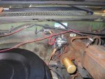
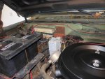
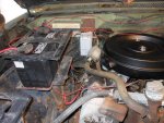
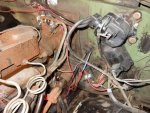
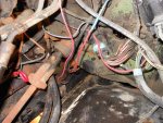
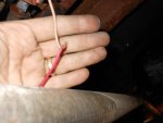
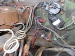
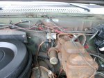
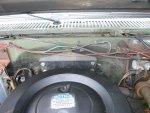
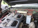
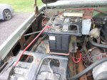
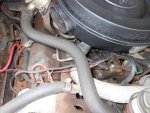
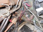
I just picked up a new truck and the PO had a mechanic who ascribed to the "Bubba" philosophy off wiring. I think he wired the manual GP button to the GP relay with the two red wires on the relay. any other help decoding the wiring would be appreciated.


The "wait" light does come on as normal, but I don't think it's activating the GP switch under the hood. It has a GP controller card installed.


thanks, David
 

Attachments

M923driver

New member
149
4
0
Location
Guntersville, AL
The wait light is controlled by a temp sensor, sounds like Bubba left that part alone. Do you want the manual GP switch or are you putting it back to stock? If you are using the switch, the controller card isn't being used as you are manually energizing the GP relay. CUCV Electric (on Ebay) has a wiring/troubleshooting guide for cheap and they also sell an updated controller card. The TM's will show you how to trouble shoot it as well, my guess is that the card went bad and Bubba just hooked up a switch instead of fixing it. Only problem with the switch is that sooner or later you'll leave it on and fry your plugs. Good luck, the TM's are your friend!
 

Warthog

Moderator
Super Moderator
Steel Soldiers Supporter
13,775
227
63
Location
OKC, OK
Does'nt look as bad as some I have seen.

Let's start with one wire at a time. And we will be removing all the Bubba wiring.

1) First thing I see is the pink wire at the IP is either being used for a hotwire or is being fed power.

Following the wire from the IP back across the firewall it "looks" like it turns into a blue wire and goes thru the firewall. Verify that and see where it goes in the cab.

2) Second. The 24v Resistor pack has been bypassed and is getting 12v to the GP relay. It looks like it is attached to the negative terminal of the rear battery. You can leave that wire in place or clean it up by attaching the wire to the 12v buss bar next to the GP relay. I like the wiring to look clean.

Do you want to leave the GPs 12v or take it back to the stock 24v?

3) There are four other wires I need you to trace.

A) There is a wire coming off the 12v terminal block with a red fuse holder. Where is it going?

B) There is a yellow connector on the GP relay. Where is that wire going?

C) There is a blue connector on the GP relay. Where is it going?

D) There is another fuse holder that looks to be grounded to the firewall. Where is it going?

Are there any wiring mods under the dash?

I am assuming some of the above wires go to the manual switch in the cab.

Remember....How do you eat and elephant? One bite at a time.

It may take a little bit but we will get thru it.

At some point you may have to take the wiring harness plug apart and clean it. We will do that if needed.
 
Last edited:

82ABNMP

Active member
Steel Soldiers Supporter
556
53
28
Location
Winston Salem NC
Thank you!

Joe thanks a bunch!! I do want to put it back as close to stock as possible. I have one of Johns new Gp card ready to install and a new GP switch. I will track all wires and report back. PO also installed a new gas tank and it looks like the bigger red wires that run under the drivers side cab go back to the tank.

I am fine with hooking the GP relay to the 12v block next to the switch as it's cleaner than running all the way to the battery. Does it matter which post I pull the 12v from on the block? He did cut both sides of the resistor pack so I will just remover that.

:beer:David
 

Warthog

Moderator
Super Moderator
Steel Soldiers Supporter
13,775
227
63
Location
OKC, OK
I like to use the bigger of the two terminals. Both work the same, but the ring connectors fit the larger better.

All you need for a manual GP switch is a ground wire and a switch. The pink and black wire at the GP relay is hot when the key is on. The controller card closes the ground when needed.

So when you need to manually energize the GPs, close the ground wire , the relay will energize and supply power to the plugs.
 

Attachments

Last edited:

MarcusOReallyus

Well-known member
4,524
810
113
Location
Virginia
:?:

I don't see a fused ground, but then, some of that diagram is a bit small for my eyes.


Are you referring to the switched ground on the upper left?
 

Warthog

Moderator
Super Moderator
Steel Soldiers Supporter
13,775
227
63
Location
OKC, OK
It's the fuse that looks to be grounded in the first picture.
 

MarcusOReallyus

Well-known member
4,524
810
113
Location
Virginia
Ah, there it is! And using a black oxide screw, no less! :shock:

I was looking at the diagram.


Yes, that's, uh, intriguing. Bubba has outdone himself! aua

rofl
 

MarcusOReallyus

Well-known member
4,524
810
113
Location
Virginia
I just ran that by my wife, who is emphatically non-mechanical, and my oldest son, who has no training yet but aspires to be a mechanic someday.

They were both shocked at the fused grounding wire.


Like I said, the best way is usually to yank it and start over. :D
 

82ABNMP

Active member
Steel Soldiers Supporter
556
53
28
Location
Winston Salem NC
Bubba strikes again...

The truck has a stereo maybe the ground is for that...I will track the wires Joe listed and report back.

aua

David
 

M923driver

New member
149
4
0
Location
Guntersville, AL
I can see no reason to fuse a ground wire except for ignorance. I agree with the previous advice: rip it out and wire it neatly and correctly. And do the Doghead starter relay while you've got your electrical tools out,
 

82ABNMP

Active member
Steel Soldiers Supporter
556
53
28
Location
Winston Salem NC
Bubba strikes again

Does'nt look as bad as some I have seen.

Let's start with one wire at a time. And we will be removing all the Bubba wiring.

1) First thing I see is the pink wire at the IP is either being used for a hotwire or is being fed power.
Following the wire from the IP back across the firewall it "looks" like it turns into a blue wire and goes thru the firewall. Verify that and see where it goes in the cab.
This wire runs way down below the cab to the fuel tank to power an electric fuel pump ( see Picture)


2) Second. The 24v Resistor pack has been bypassed and is getting 12v to the GP relay. It looks like it is attached to the negative terminal of the rear battery. You can leave that wire in place or clean it up by attaching the wire to the 12v buss bar next to the GP relay. I like the wiring to look clean.

Do you want to leave the GPs 12v or take it back to the stock 24v?

I cut the bubba wire off the rear battery and attached a new 12v wire to the 12v power block.

3) There are four other wires I need you to trace.

A) There is a wire coming off the 12v terminal block with a red fuse holder. Where is it going? Orange wire from 12v block turns into black wire going through the firewall and is the power source for the brake control. Disconnected.

B) There is a yellow connector on the GP relay. Where is that wire going?
this wire is part of the manual GP button. Disconnected.

C) There is a blue connector on the GP relay. Where is it going?
Second wire for the Manual GP button. Disconnected.

D) There is another fuse holder that looks to be grounded to the firewall. Where is it going? This ire was the ground for the brake control. Disconnected, and re attached to the ground bus under the driver side dash.

Are there any wiring mods under the dash? Yep, he has a 12v power into the fuse box for the cigarette lighter.

I am assuming some of the above wires go to the manual switch in the cab.

Remember....How do you eat and elephant? One bite at a time. Have taken the first bite

It may take a little bit but we will get thru it.

At some point you may have to take the wiring harness plug apart and clean it. We will do that if needed.
After disconnecting everything I installed a new GP card, new GP relay and cleaned everything on the 12v block, installed a new 12v power wire to the GP relay, and installed a new starter switch along with 2 new relays, one for Gen 2 and one for the Volt meter. The truck now fires right up and goes through the GP cycle. i need to now re-install power for the brake control...where should I pull it from?


The big question at this point is the pink wire going from the IP hot wire way down under the truck to the ( i think) power of the aftermarket fuel pump? Why do this...can't I get power from a better source?

Thanks, for the help! David
 

Attachments

Last edited:

kingchr

New member
19
0
1
Location
Prospect/Oregon
Fuel Pump Wiring

Yes, yes there is. When I do this conversion on a truck, I tap the ign line in the fuse block to actuate a relay (like the blower fan relay that we remove from the starter circuit when we do a doghead mod. I then use a fused (usually 10a) constant hot (like tapping the same 12v bus as your gp relay) to feed the relay. I like using the blower relay, as you now have a spare driving your fan if you have an emergency and need to get the fuel pump working again.

Good luck,
Christopher
 
Top
AdBlock Detected

We get it, advertisements are annoying!

Sure, ad-blocking software does a great job at blocking ads, but it also blocks useful features of our website like our supporting vendors. Their ads help keep Steel Soldiers going. Please consider disabling your ad blockers for the site. Thanks!

I've Disabled AdBlock
No Thanks