• Steel Soldiers now has a few new forums, read more about it at: New Munitions Forums!

  • Microsoft MSN, Live, Hotmail, Outlook email users may not be receiving emails. We are working to resolve this issue. Please add support@steelsoldiers.com to your trusted contacts.

Can someone explain isolated ground?

Warthog

Moderator
Super Moderator
Steel Soldiers Supporter
13,774
232
63
Location
OKC, OK
Turns out his alternator was not rebuilt correctly. The repair shop "forgot" to install the fiber washer on the inside in the case for the ground post.

This allowed the ground post and case to connect and this in turned caused a direct short of the battery to the case ground.
 

UncleSam

New member
58
3
0
Location
Anniston Alabama
Isolated Ground Rebuild Kit??

Warthog, Will the complete rebuild kit from CUCVElectric work in either alternator? Isolated ground #2 Alt or #1 Alt ?


Turns out his alternator was not rebuilt correctly. The repair shop "forgot" to install the fiber washer on the inside in the case for the ground post.

This allowed the ground post and case to connect and this in turned caused a direct short of the battery to the case ground.
 

doghead

4 Star General /Moderator
Staff member
Super Moderator
Steel Soldiers Supporter
26,246
1,178
113
Location
NY
It should, the alts are identical.
 

Warthog

Moderator
Super Moderator
Steel Soldiers Supporter
13,774
232
63
Location
OKC, OK
Warthog, Will the complete rebuild kit from CUCVElectric work in either alternator? Isolated ground #2 Alt or #1 Alt ?
The kit will work just fine in any type 27SI alternator. That is the type of alternator the "isolated ground" units are.

The only parts that are not in the kit are the fiber washers and "ground" terminal post that are unique to the military unit.

99% of the time the old ones are reusable.

The electronics are the same as the civvy alternators.

The TM 9-2320-289-34 techniacal manual has a step-by-step procedure to rebuld the alternator.

Take pictures the first time you do one. It helps you remember where all the screws and stuff goes.
 

UncleSam

New member
58
3
0
Location
Anniston Alabama
Thanks, I printed out the pages that cover that in TM 9-2320-289-34, I wasn't sure that the kit would work, I'll save the fiber washers...

My #1 Alternator is putting out 14+V But the #2 is about 13.5V and the #2 Gen light is flickering at idle, and I thought that it needed a rebuild..

Thanks again,
UncleSam


The kit will work just fine in any type 27SI alternator. That is the type of alternator the "isolated ground" units are.

The only parts that are not in the kit are the fiber washers and "ground" terminal post that are unique to the military unit.

99% of the time the old ones are reusable.

The electronics are the same as the civvy alternators.

The TM 9-2320-289-34 techniacal manual has a step-by-step procedure to rebuld the alternator.

Take pictures the first time you do one. It helps you remember where all the screws and stuff goes.
 

acesneights1

Member
1,449
22
20
Location
CT
I'll be the dope and ask, why not just use one 24v alt ?? I never got that. So the alts are in series to produce 24v to charge the 2 batts which are in series ? Why were two 12v alts necessary ?
 

Warthog

Moderator
Super Moderator
Steel Soldiers Supporter
13,774
232
63
Location
OKC, OK
SImple terms:

Under ideal conditions (not very often) the alternaters are charging in series. Most of the time they are charging the individual batteries.

You use 24v to start and run the glowplugs on a stock system.

All the other time you are only pulling 12v from the front battery. The rear is just sitting there most of the time.

If you used a 24v alternator it would not charge the front battery and and would cook the rear battery
 
Last edited:

acesneights1

Member
1,449
22
20
Location
CT
That is the part I don't get. I have worked on alot of payloaders exacvators etc which use 2 12vbatts in series but one 24v alt. So you are saying one alt charges each batt but how is that possible if the second alt is putting out 24v on the output ?? Is the drivers side alt charging just the front batt and the drivers side and pass side alt combined somehow charging both ?
 

Warthog

Moderator
Super Moderator
Steel Soldiers Supporter
13,774
232
63
Location
OKC, OK
If the excavators are 24v systems, then 2 twelve volt batteres will work fine with the 24v alternator.

The issues arises when you are pulling 12v out of the middle of the circuit. It drains voltage from only half of the 24v total.

The M1010 Ambulace has a large need for 24v power. And a smaller need for 12v. In this vehicle they do use a 24v alternator BUT they also have to have a DUVAC power converter to charge just the front battery.

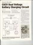
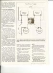
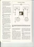
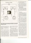
A fellow member, AMPHI, conducted an experiment with the CUCV system and wrote an article for MV Magazine.

Here is the copywrited article. It may help explain it better.
 

Attachments

JustStoner

New member
8
0
0
Location
Farmington, NM
Ok here is the story. I bought an 85 m1009 I took it to a mechanic to fix the bigger problems. He explained that it wasn't a 24 volt system, both alternators were bad and I didn't need two. I put a new one on the passenger side and grounded it to the frame. I put in new the battery wires and wired the batteries in parallel. It would turn over slowly but not start. I put in new glow plugs and controller from DieselRx (not sure if I wired the controller correctly). My brother told me to wire the batteries in series. It turned over with no problems until I smelled something electrical burning. It was the card under the dash. CRAP!

My questions are. How do I wire the batteries correctly so I don't burn the Blazer to the ground? Do I need two alternators? And can anyone help me wire the new style GP (DRX-DRX01005_ml.jpg) controller so I don't waste more money?

Thanks
 
Last edited:

Warthog

Moderator
Super Moderator
Steel Soldiers Supporter
13,774
232
63
Location
OKC, OK
Start a new thread with your problem. This thread is not the place.

Your mechanic just cost you some money an a lot of headaches. Time to find a new mechanic.

Yes it is fixable but a bunch of steps are required.
 

MarcusOReallyus

Well-known member
4,524
816
113
Location
Virginia
I know this is an old thread, but for the sake of anyone reading through and trying to understand the system, I think this needs to be pointed out:

I can't explain with the CUCV.
That's a correct statement, and he should have stopped there.

The rest of it is completely wrong.

But in General. Isolated ground is where you have two ground paths for a system to avoid adding RF noise to something.
/shaking my head/

This is a classic case of a little knowledge being a dangerous thing. The systems he describes have nothing to do with the isolated ground of a CUCV. They are done for completely different reasons, and they work in a completely different manner.

The flashlight battery example given by magnus is a good example. If you are trying to understand the CUCV system, that's a great place to start.
 
Top