• Steel Soldiers now has a few new forums, read more about it at: New Munitions Forums!

  • Microsoft MSN, Live, Hotmail, Outlook email users may not be receiving emails. We are working to resolve this issue. Please add support@steelsoldiers.com to your trusted contacts.

Charging system woes

frontiersman

New member
77
0
0
Location
Tuscaloosa, AL
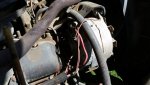
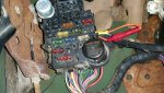
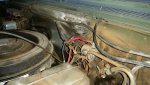
Hi all, I am a newbie to cucv trucks. Always wanted one, and 2 weeks ago finally got an m100 that came from camp shelby. Thanks to the immense knowledge base here, I was able to get the truck running great. It apparently had been kept up pretty good until decommissioned. Since day 1 when I turn the key on, there no lights that come on the dash. The 12v junction block looks busted, and at some point the military bypassed it. The 24v resistor bank is completely gone, and there is a lead coming from the jumper battery cable that supplies 12v to the glow plug relay. The entire harness for the glow plugs looks new, as well as the glow plugs. I did the doghead mod as well. All running lights work, and the dash illumination lights work. Here is my problem; the alternators are producing voltage, but the batteries die after several starts. I also have to "jump" the glow plug relay with a jumper wire to make it work. I am going to install a push button switch to solve that problem. A couple of questions: can the generator relays under the dash be bypassed, as well as the fabled gen idiot lights? I not concerned with keeping it all military stock. In theory could run a cable from the drivers side positive to the passenger side negative to achieve 24v charging? I really dont care if the idiot lights work, as I plan to install mechanical gauges. Also, the stock voltage meter does not work. Attached is a pic of the wiring mess I am dealing with. Thanks
 

Attachments

frontiersman

New member
77
0
0
Location
Tuscaloosa, AL
When referring from bypassing the generator relays and idiot lights, I was referring to running a cable between the 2 alternators. Also the truck is an M1008.
 

tim292stro

Well-known member
2,118
39
48
Location
S.F. Bay Area/California
I believe the idiot lights are actually what powers the voltage regulator in the alternator - not powering those (and having the entire charing system in good repair) will prevent the alternator from outputting current.

The power to the idiot light is 12v RELATIVE TO THAT ALTERNATOR'S GROUND. This is important if your thinking of connecting the two idiot light circuits together - you'll either ground the top alternator's idiot light circuit (no charge high battery), or blow up the voltage regulator on the low side. Best not to mess with the circuit design...

What voltage did you measure while the truck was running? It should be something like 13.8-14.4v per battery while charging.
 
Last edited:

frontiersman

New member
77
0
0
Location
Tuscaloosa, AL
I have a very cheap voltmeter that isn't digital. I checked the output on both alternators. The driver side is a little above 12v and the passenger side is much more. Again, I am a newbie. I cannot find why no idiot lights whatsoever comes on when the key is on. I pulled the instrument cluster out yesterday and cleaned all contacts and installed all new bulbs. What works in the cluster is signal indicators, high beam indicator, illumination lights. Fuel gauge only works when I jump the glow plug relay. All I need is for the system to charge the batteries without rewiring a pile of stuff, and spending a lot of money. Have talked to a couple of other owners and they were helpful, but they really can't help me without having hands on.
 

tim292stro

Well-known member
2,118
39
48
Location
S.F. Bay Area/California
Even a cheap digital DMM is likely to give a voltage in the +/-0.2V accuracy range - an analog multimeter will need to be calibrated to be of much use, and if the gauge is too small, it becomes pretty useless (i.e. if the sweep of the needle goes from 12V to 13V in less than 1/8", it's probably not worth your time).

I'd recommend pulling the alternators and taking them to a parts house to have them tested (should be free, or at least really cheap) - the isolated ground alternators should still be easy for them to test - just make sure you tell them that one of the lugs is ground (not the case). Once you have verified the alternators are good, check your fusible links - not just for continuity, but also for current capacity. These are the primary battery to alternator wires, without them the alternator has no power to run or "push against" to charge. I've heard of fusible links partially burning and supporting a small voltage (continuity test) but not able to carry current (like that from a headlight bulb).

Check your grounds... then check the voltages for the idiot light circuit while the engine is running. The ignition switch should power one side of the light bulb, so when you turn on the ignition switch you should be able to see a voltage to ground (12V for the low-side, 24V for the high-side). When the alternator is running the idiot light terminal (brown wire) will pull low (should turn on the idiot light) to test the light, then when the field energizes and the alternator begins producing power, that terminal should rise to the output voltage of the alternator (causing both sides of the idiot light to be nearly the same voltage, extinguishing the idiot light). If the alternator fails to generate power any time after the "test" startup delay, the idiot light terminal should again drop to that alternator's ground potential - causing the idiot light to illuminate.

Obviously, you want to get a copy of the Technical Manual(s) for the CUCV, if you don't have them already. Here is a useful diagram of the CUCV charging system from that TM:

ChargingDiagram.jpg

I have found most TM's to be very clear and easy to follow, these were used to train guys who had never touched these trucks, how to deal with them.
 

tim292stro

Well-known member
2,118
39
48
Location
S.F. Bay Area/California
A 12V lead acid battery is made up of six 2volt cells in series, to charge a lead acid battery you need between 2.30-2.4volts per cell (13.8-14.4V). Any lower and your battery will not charge - you'll be running loads from the battery as it discharges, until it's flat/dead at around 11.7V at rest (no loads). 12Volts showing while under a light load means your battery is actually under 20% charged - kind of misleading when we call it a 12V battery. A fully charged 12V battery should read around 12.6V at rest (no load).

If your low-side battery (positive terminal to chassis = 12V, driver' side IIRC) is not charging this will have the greatest impact on your truck while running - the Chevy is 12V for everything except the glow plugs and starter motor, and runs off the low battery. failure to charge that battery will lead to being dead on the side of the road. The high-side battery (positive terminal to chassis = 24V, passenger's side IIRC) only runs the starter motor, glow plugs (through the ballast resistor) and connects to the NATO plug - that's it.

The relay for the gen light should use the 12V ignition signal that also powers the low-side idiot light to energize the relay coil. The switched terminals of the relay should connect +24 high side battery positive to the high-side alternator's idiot light in place of the ignition wire. In this way, the 12V ignition circuit uses the relay to create a 24V ignition circuit, so the 12V and 24V systems are essentially identical (just one of them is shifted up 12V).
 

MarcusOReallyus

Well-known member
4,524
811
113
Location
Virginia
Best not to mess with the circuit design...

This is excellent advice. PLEASE heed it. The shortest distance between where you are now and a reliably running truck is through repairing the existing design. All the knowledge is here, and there are plenty of people who will help you get there.

The longest, hardest, and most expensive and painful path is a re-design. Please don't go that way.


Look at it this way: You are a newbie with limited knowledge of electricity. There are quite a number of people on this forum who are engineers who make their living with electricity, and none of us have tried to re-design the charging system. Think there might be a reason for that?

The only redesign that anybody has done that is reasonable is known as the Roscommon method, which is converting it to twelve volts instead of 24. Even if you were to go that route, you'd still need to do basic troubleshooting and repairing to get where you want to go.


I have a very cheap voltmeter that isn't digital.
Fix that first. Even a $10 cheapo from Lowe's will do you fine.

Take it one step at a time, follow directions, answer questions, and this forum will get you where you want to go.


:beer:
 
Last edited:

Warthog

Moderator
Super Moderator
Steel Soldiers Supporter
13,775
227
63
Location
OKC, OK
Looks like to only wiring hacking is at the 12v power terminal. There was a short and a small fire at some point.

The easiest and best way to fix your issues is to fix that spot.

A diamond shaped terminal block can be had at almost any pull-a-part yard. I may even have a couple in my parts pile.

Start with the basics and rebuild that spot and everything should fall into place.

If you do not have electrical experience you will be in a world of hurt trying to "redesign" the system.

A couple of questions: can the generator relays under the dash be bypassed, as well as the fabled gen idiot lights?
The easy answer is No. Both are required to make the system function. The idiot lights are part of the design of the alternator exciter circuit. If they do not work, the alternators will not excite. There is only one relay for the GEN2 exciter circuit. The other is for the volt meter.

In theory could run a cable from the drivers side positive to the passenger side negative to achieve 24v charging?
While that would seem like it would work, in reality it will not. In the factory setup there are three wires that meet at the 12v terminal block. One from the front battery positive terminal, one from the driver side alternator positive terminal and the last from the passenger side alternator "ground" terminal. With it wired this way the system has the proper path to send current to each of the batteries. If you take out one of the wires you loose that path.

Here is a sticky that help explain the circuit

http://www.steelsoldiers.com/showth...ternator-Isolated-Ground-Therory-of-Operation


Last edited:

frontiersman

New member
77
0
0
Location
Tuscaloosa, AL
Thanks everyone for the help. I am guessing, just guessing, that of I rebuild the hacked up wiring that went to the 12v junction it "may" allow power to come to the instrument cluster? As it is right now none of the idiot lights work ever. Whoever hacked the wires did get one thing right that works tbough, they ran a 12v lead from the jumper cable to the glow plug relay (bypassing the 24v resistor bank, which is gone). It also appears that they made a new glow plug harness and installed new glow plugs. I can manually make them work by jumping them at the relay. Now, does anyone have a part number for the diamond shaped 12v junction block and a picture that shows what wires go to it? Thank you again everyone!
 

Warthog

Moderator
Super Moderator
Steel Soldiers Supporter
13,775
227
63
Location
OKC, OK
All of your issues are common ones that have been address here many times. The CUCV Helpful Threads sticky has many of the common issues listed.

http://www.steelsoldiers.com/showthread.php?123199-CUCV-Helpful-Threads

All the part numbers are in the free parts manuals that are available here. You have download the manuals haven't you?

http://www.steelsoldiers.com/showthread.php?77609-TM-s-for-the-CUCV

The hack in the fuse box is for the headlight fuse. If you look closely the fuse box next to the yellow crimp connector is melted. This is a very common problem.

Also you have some fuses missing in the fuse box that will have an effect of the alternators. The very top fuse is missing. It controls the heater and GEN1. (crazy I know).

Also the fuse for the ignition circuit is missing (next to the bright yellow fuse)

Here is a sticky that covers all the fuses (which are needed to make you truck work properly)
http://www.steelsoldiers.com/showthread.php?132309-CUCV-Fuse-Box-Layout

The 12v terminal block can be found in the TM 9-2320-289-34P parts manual, Figure 65, item #7

GM part number 3996270

The broken wire is for the diagnostic port. It is not need and you can just tape it up and zip tie it.
 
Last edited:

tim292stro

Well-known member
2,118
39
48
Location
S.F. Bay Area/California
...The shortest distance between where you are now and a reliably running truck is through repairing the existing design...
...The longest, hardest, and most expensive and painful path is a re-design...
I know he's agreeing with a post of mine, but in regards to the second statement - I can speak from experience that he is absolutely correct (example #1, example #2). If you don't have a VERY GOOD REASON to modify the original design, you will be best served by the original design. In my case, I have a good reason and a decade and a half of experience to prepare me.

I also agree with Warthog that this is probably related to only the 12V system issues where you have already noticed "hacking up". Fix that and you're very likely good to go.
 

frontiersman

New member
77
0
0
Location
Tuscaloosa, AL
Ok, replaced many fuses, some were missing and a couple blown. What started working is all idiot lights except Gen 1. I put a fuse in the top slot that was missing (heater blower I believe). Gen 1 light never came on and fan motor didn't work. It also popped the fuse. Replaced with a new fuse, didn't pop this one, but still no gen 1 light or fan power. God I don't want to pull the fuse box, I'm an idiot with electric stuff as is.
 

tim292stro

Well-known member
2,118
39
48
Location
S.F. Bay Area/California
Did it pop the fuse when you tried to turn on the blower, or did it just blow when you turned on the ignition? You can remove the bulb from the gen1 light, and stuff a fuse in there again to see if it blows - if so, it's likely your blower causing the fuse to let go. Once you do that check you can start to narrow down the component that is causing the fuse to pop.

One other thing you can try to see if it's something in the idiot light circuit, is to use a simple $4 test light from the output of the alternator and the idiot light terminal. This will simulate the idiot light circuit without the rest of the hacked wiring coming into play - with the engine stopped the light should turn on, but with the engine running it should turn off and the alternator should charge the battery (13.8V-14.4V).
 

cucvrus

Well-known member
11,297
9,732
113
Location
Jonestown Pennsylvania
Clean the back side of the instrument cluster circuit board. Wiggle the bulb / sockets around in the mounts. See if that helps. Switch the known working bulb and socket into the non working socket. Bend the tabs on the socket and clean them. See if you have a bad bulb. Anything can make this condition. Check your fusible links under the hood. Difficult at times to pin point but as a rule follow the test procedure and you should be good. Good Luck. If you were closer I would help you out. Good Luck again.
 

Warthog

Moderator
Super Moderator
Steel Soldiers Supporter
13,775
227
63
Location
OKC, OK
The GEN1 bulb should be a 168 along with all the others except for GEN2 and the bulb for the fuel guage (194)

168 is a 5w bulb
194 is a 3w bulb
 

frontiersman

New member
77
0
0
Location
Tuscaloosa, AL
I may have fixed the charging issue. I got the Gen 1 light to come on when you turn the switch on. The switch is cycling the glow plugs too. I have to cycle then a couple of times, and it starts right up. Drivers side alt is producing 12.5 - 13 volts. Pass side producing 27-28 volts. Battery front reads 12.8, back battery reads 13v. Across both is 28 and some change. However, Gen 1 light stays on. The brake light indicator and low coolant light stay on as well.
 
Top