• Steel Soldiers now has a few new forums, read more about it at: New Munitions Forums!

  • Microsoft MSN, Live, Hotmail, Outlook email users may not be receiving emails. We are working to resolve this issue. Please add support@steelsoldiers.com to your trusted contacts.


Control Box Schematics

papakb

Well-known member
2,288
1,186
113
Location
San Jose, Ca
I originally posted this as a reply on another posting and I don't think it was getting the visibility it needed. I think this would be an excellant forum to get this information out to the group so that we could possibly develope a decent final design. Lord knows, Uncle hasn't been able to! We've got some smart people here that have actually worked on these things and understand them better than some design engineer sitting at a desk somewhere.

My question is: what were the original designs (schematics) and how can we improve them or create a design that eliminates all the expensive options we now have?

Original post:

Speaking of schematics, has anyone ever come across real, full schematics for any of the boxes? The manuals are only vague about them and the diagrams are only representative of the signals in and out of them. And half of them aren't readable because they've been copied so many times! There's been a lot of reverse engineering done on the different models but I don't think I've ever seen a true schematic for them.

If anyone has them would you please post them here?

THANKS
 

Milcommoguy

Well-known member
Supporting Vendor
1,653
2,098
113
Location
Rosamond, CA
I originally posted this as a reply on another posting and I don't think it was getting the visibility it needed. I think this would be an excellant forum to get this information out to the group so that we could possibly develope a decent final design. Lord knows, Uncle hasn't been able to! We've got some smart people here that have actually worked on these things and understand them better than some design engineer sitting at a desk somewhere.

My question is: what were the original designs (schematics) and how can we improve them or create a design that eliminates all the expensive options we now have?

Original post:

Speaking of schematics, has anyone ever come across real, full schematics for any of the boxes? The manuals are only vague about them and the diagrams are only representative of the signals in and out of them. And half of them aren't readable because they've been copied so many times! There's been a lot of reverse engineering done on the different models but I don't think I've ever seen a true schematic for them.

If anyone has them would you please post them here?

THANKS
I just had this discussion with a couple members. Reverse engineering is a thing, as in a word... CHINA. Another word is PROPRIETARY... hence the fuzzy, lack of info about these boxes under the dash or on paper.... along with how it works or doesn't work.

My experience with auto shop 101 is most can turn a wrench... only a few get it when it the electricity is turn on. I am NOT saying anyone is dumb, but it is a little harder to wrap your hands around it. Can be a little tricky, but not magic.

IMO and others... For what every the reason, HumV's designers went way overboard. Place your thoughts and comments here__________________________. That would be fun to see.

There is sort of a scale to cost here. What I mean is, One just dropped 10, 20 , 30 K $ on a thirty year old truck to get into the hobby. Looking at bringing it up to safe road worthiness, and that's a subjective mouthful... tires, batteries, license, insurance, that's not including all the nuts and bolts... things that make it go and stop. Then there's one's personal vision to jazz it up. How much did that cost? I am not asking.... I am checking with the wife on this question.

So my question would be... what would one pay to have a "box" that meet the hobbyist needs? Don't low ball it either... remember I am talking to the BOSS, lol.

Here's another word. Good old Yankee ingenuity is already at work, with time and money taking the magic out of the box. It is being done as I write this little teaser.

Serious as a hot glow plug, CAMO

Stand by for a follow up. Working it out....

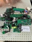
thumbnail.jpg
 
Last edited:

donquijote

Active member
166
36
28
Location
Louisiana
I'm getting on upwork next week and hiring an electrical engineer to just make us some schematics for a bypass system. This can't be rocket science and I have zero doubt it should be very easy for an experienced engineer.

Sent from my SM-G986U using Tapatalk
 

Milcommoguy

Well-known member
Supporting Vendor
1,653
2,098
113
Location
Rosamond, CA
I'm getting on upwork next week and hiring an electrical engineer to just make us some schematics for a bypass system. This can't be rocket science and I have zero doubt it should be very easy for an experienced engineer.

Sent from my SM-G986U using Tapatalk

NO... it not rocket science. But a launch is about to happen🚀

For the HMMWV owners there will be a "bullet proof" kit available soon. A few units of my design have been built and I am following the progress. ( a little cat named "beta test" got out of the bag here on SS and face book)

With the ongoing surplus HMMWV sales and failing "boxes"... this option meets the hobbyist / DIYer's needs and budget. I am 100 % committed and dollars invested to have a deliverable product by mid February.

Serious inquires to be put on the list send PM to my "milcommoguy" here on SS.

Count down has begun, CAMO
 

Mogman

Moderator
Staff member
Moderator
Steel Soldiers Supporter
5,919
8,241
113
Location
Papalote, TX
NO... it not rocket science. But a launch is about to happen🚀

For the HMMWV owners there will be a "bullet proof" kit available soon. A few units of my design have been built and I am following the progress. ( a little cat named "beta test" got out of the bag here on SS and face book)

With the ongoing surplus HMMWV sales and failing "boxes"... this option meets the hobbyist / DIYer's needs and budget. I am 100 % committed and dollars invested to have a deliverable product by mid February.

Serious inquires to be put on the list send PM to my "milcommoguy" here on SS.

Count down has begun, CAMO
Do you have an approximate price point?
 

mgFray

Well-known member
Steel Soldiers Supporter
656
907
93
Location
Southern Minnesota
For what the box does, in an all in-one "pre-built" config. $250-$500... Maybe my prices are out of whack from reality, but I'm basing it off of different power regulators and such I've had to buy for other (civilian) vehicles which tend to be closer to the $250 range, unless they're full of fuses and expansions.. then might get upwards of $500.
 

Milcommoguy

Well-known member
Supporting Vendor
1,653
2,098
113
Location
Rosamond, CA
For what the box does, in an all in-one "pre-built" config. $250-$500... Maybe my prices are out of whack from reality, but I'm basing it off of different power regulators and such I've had to buy for other (civilian) vehicles which tend to be closer to the $250 range, unless they're full of fuses and expansions.. then might get upwards of $500.
Thank's for your input, CAMO
 

NDT

Well-known member
Steel Soldiers Supporter
10,163
5,843
113
Location
Camp Wood/LC, TX
My suggestion would be to offer new "guts" for the existing boxes we have. That will eliminate the expense of the box and the expensive connectors. And pppplease use a big honkin solenoid, not those 3 in a row transistors to light up the glows.
 

mgFray

Well-known member
Steel Soldiers Supporter
656
907
93
Location
Southern Minnesota
My suggestion would be to offer new "guts" for the existing boxes we have. That will eliminate the expense of the box and the expensive connectors. And pppplease use a big honkin solenoid, not those 3 in a row transistors to light up the glows.
Curiosity has me on this one. Looking up some things, I see a lot of modern glow plug controllers use mosfets instead of solenoids specifically so they can control the plug using a PWM (pulse with modulated) circuit to better control the heating of the glow plug itself, especially based on the current engine temp ranges.

Does anyone know if the current design of the EESS boxes uses PWM for the control, which is why they have the mosfets and not a single big honkin solenoid?

I also stumbled on something talking about some plugs are 'self-regulating', doubt we have those, but it went on to say the resistance on the plug changed based on the plug temp. Lower the temp, higher the resistance, but it did require the controller to have a current sensing circuit to ensure that when resistance approached 0, the circuit was turned off (as the plug could be damaged otherwise).
 

Mogman

Moderator
Staff member
Moderator
Steel Soldiers Supporter
5,919
8,241
113
Location
Papalote, TX
Curiosity has me on this one. Looking up some things, I see a lot of modern glow plug controllers use mosfets instead of solenoids specifically so they can control the plug using a PWM (pulse with modulated) circuit to better control the heating of the glow plug itself, especially based on the current engine temp ranges.

Does anyone know if the current design of the EESS boxes uses PWM for the control, which is why they have the mosfets and not a single big honkin solenoid?

I also stumbled on something talking about some plugs are 'self-regulating', doubt we have those, but it went on to say the resistance on the plug changed based on the plug temp. Lower the temp, higher the resistance, but it did require the controller to have a current sensing circuit to ensure that when resistance approached 0, the circuit was turned off (as the plug could be damaged otherwise).
No self regulating glow plugs, the afterglow on the HMMWV is PWM thus the reason to use FETs
 

Mogman

Moderator
Staff member
Moderator
Steel Soldiers Supporter
5,919
8,241
113
Location
Papalote, TX
I'm getting on upwork next week and hiring an electrical engineer to just make us some schematics for a bypass system. This can't be rocket science and I have zero doubt it should be very easy for an experienced engineer.

Sent from my SM-G986U using Tapatalk
It does not require an engineer to figure out what the EESS does, the basic functions can be done with two relays, in fact one of the functions is already done with a relay or relays depending on the model EESS, and that relay is one of the failure points on the EESS, the only way to make it "bulletproof" is to use a relay with a very high silver content in the contacts (read expensive) and designed to be stuffed into a box with no air circulation, most continuous duty relays are designed for "open air" installations.
 

donquijote

Active member
166
36
28
Location
Louisiana
It does not require an engineer to figure out what the EESS does, the basic functions can be done with two relays, in fact one of the functions is already done with a relay or relays depending on the model EESS, and that relay is one of the failure points on the EESS, the only way to make it "bulletproof" is to use a relay with a very high silver content in the contacts (read expensive) and designed to be stuffed into a box with no air circulation, most continuous duty relays are designed for "open air" installations.
What are the other failure points besides the cheap relays? And no, it doesn't technically need and engineer if you have knowledge of electronics design. But I figured someone who does this for a living would design the most robust system in less time than me trying to figure it out.

Sent from my SM-G986U using Tapatalk
 

TOM R

Active member
227
81
28
Location
sewell n.j.
It does not require an engineer to figure out what the EESS does, the basic functions can be done with two relays, in fact one of the functions is already done with a relay or relays depending on the model EESS, and that relay is one of the failure points on the EESS, the only way to make it "bulletproof" is to use a relay with a very high silver content in the contacts (read expensive) and designed to be stuffed into a box with no air circulation, most continuous duty relays are designed for "open air" installations.
I'm running the camo box now and so far works perfectly
 

Mogman

Moderator
Staff member
Moderator
Steel Soldiers Supporter
5,919
8,241
113
Location
Papalote, TX
What are the other failure points besides the cheap relays? And no, it doesn't technically need and engineer if you have knowledge of electronics design. But I figured someone who does this for a living would design the most robust system in less time than me trying to figure it out.

Sent from my SM-G986U using Tapatalk
The most common failure point is the FETs that short and blow out the glow plugs and or blow themselves up.
 

Mogman

Moderator
Staff member
Moderator
Steel Soldiers Supporter
5,919
8,241
113
Location
Papalote, TX
I'm running the camo box now and so far works perfectly
I would expect a box with high quality relays would be very dependable, but when you use a relay to switch on and off a DC load material is transferred from one contact to the other, eventually this causes a high resistance between the contacts which makes the problem worse until it can no longer carry a load.
Now that point can be 5-10-15 years down the road depending on the material the contacts are made of and the amount of load that is switched and the number of times the load is switched.

Now do not misunderstand if I was going to design a cost effective and relatively foolproof replacement for the "box" relays are the only reasonable choice.
 

NDT

Well-known member
Steel Soldiers Supporter
10,163
5,843
113
Location
Camp Wood/LC, TX
Solenoids have been used to switch on heavy DC loads like starter motors since cars didn’t have cranks. My 1968 Ford still has the factory starter solenoid with 350,000 miles.
 

Mogman

Moderator
Staff member
Moderator
Steel Soldiers Supporter
5,919
8,241
113
Location
Papalote, TX
Solenoids have been used to switch on heavy DC loads like starter motors since cars didn’t have cranks. My 1968 Ford still has the factory starter solenoid with 350,000 miles.
That may be true but the FACT is the automotive style relays used in the EESS can and have failed many times and they are not "cheap" the last one I replaced was made in Germany as best I can remember,

AGAIN not saying it is a bad idea, in fact it is the only cost effective way to replace the guts in the "box" but it also is not the only solution.

Also not all 1968 ford solenoids lasted 350,000 miles so you are citing anecdotal evidence.

Some users never have issues with the EESS box, that does not mean nobody has issues

I am sure the CAMO box will serve many well. considering the available options I think it is a great idea!
 

mrmikey

New member
4
9
3
Location
chicago
All of the info you want, is available.

I have schematics, values, part numbers...

While yes it is proprietary, some factory has the parts for sale within their catalog.

I have also personally worked on well over 1000 boxes, and keep very detailed info on them.

I use my personal truck as my test lab. Yes, it gets pricey, but I have learned a lot.
 
Top
AdBlock Detected

We get it, advertisements are annoying!

Sure, ad-blocking software does a great job at blocking ads, but it also blocks useful features of our website like our supporting vendors. Their ads help keep Steel Soldiers going. Please consider disabling your ad blockers for the site. Thanks!

I've Disabled AdBlock
No Thanks