• Steel Soldiers now has a few new forums, read more about it at: New Munitions Forums!

  • Microsoft MSN, Live, Hotmail, Outlook email users may not be receiving emails. We are working to resolve this issue. Please add support@steelsoldiers.com to your trusted contacts.

Converting tail lights to LED

TexAndy

Active member
1,427
15
38
Location
Bee County, Texas
Some guy out of hong kong is selling 100 super bright (20,000mcd) LEDs with 100 1/4watt-rated resistors for 5.75, shipped on ebay. I couldn't resist. Resist. Get it? 8)


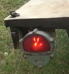
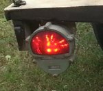
Anyways, I'm going to see if I can scrounge up some perfboard or something and wire up a drop in LED module for a standard tail light. See how it works.


This ain't exactly reinventing the wheel, so it should work. It won't be as smart as the real ones. Pretty much be stuck in the 12V to 14V, I think. But if this works, I'll be redoing the lights on my M1102, which I only plan on towing behind my chebby, anyways.

It's cheap enough that I suppose you could wire up a 24V module and swap them when you want to tow it behind a mil vehicle, tho.

Anyone else around here tried this mod?
 

gimpyrobb

dumpsterlandingfromorbit!
27,785
748
113
Location
Cincy Ohio
I'm pretty sure someone grabbed one of the round trucker tail, stop, turn lights and grafted it in the stock MV taillight. Thats the closest thing I can remember.
 

TexAndy

Active member
1,427
15
38
Location
Bee County, Texas
I'm pretty sure someone grabbed one of the round trucker tail, stop, turn lights and grafted it in the stock MV taillight. Thats the closest thing I can remember.
Interesting. Sounds too rich for my blood, tho. :D

I'm shooting for under a dollar a light, total cost (not counting my time.)
 

tim292stro

Well-known member
2,118
39
48
Location
S.F. Bay Area/California
You need between 80 and 300 candela emitted from the lens to meet federal regulations for a brake light. Figure roughly a 15% loss through the lens - figure on 6 being your absolute minimum being illuminated before you replace it - but you'll want more like 18 of those LEDs to start with.
 

TexAndy

Active member
1,427
15
38
Location
Bee County, Texas
I used these, used 2 modules for running and 5 for brake lights, they just need the 12 volts no drivers and all, kind of crude but they work for me, also put some in blackout section for reverse lights, 2cents
Very cool. How did you wire the vehicle to active the reverse lights?
 

tim292stro

Well-known member
2,118
39
48
Location
S.F. Bay Area/California
I also like a voltage regulator to reduce the voltage below the lowest droop - then the LED + resistor. This way you won't have flickering or dimming when you idle-down or turn on your windshield wipers or start the engine. Regulating down to like 7volts, then using the current limiting resistor to regulate the current for only two LEDs. One voltage regulator should work for a single light function - if you want to do two level brightness, I doubt you'll get your sub $1 per fixture budget.

Something like a LM138, would give you an input from 9-32V to your light fixture, so you could use it on either a 12v or 24v electrical system. Putting a bunch of LED strings in parallel makes the light more reliable should one LED fail open. I think (speculate) this is why Grote and TruckLite military tail lights fail so often.

You could likely do this for less than $5 per fixture.
 
Last edited:

TexAndy

Active member
1,427
15
38
Location
Bee County, Texas
I also like a voltage regulator to reduce the voltage below the lowest droop - then the LED + resistor. This way you won't have flickering or dimming when you idle-down or turn on your windshield wipers or start the engine. Regulating down to like 7volts, then using the current limiting resistor to regulate the current for only two LEDs. One voltage regulator should work for a single light function - if you want to do two level brightness, I doubt you'll get your sub $1 per fixture budget.
Sounds good. What component would you recommend?

The LEDs I'm using draw 20 mA and have a voltage drop between 1.7 and 2.3. 1.9 nominal.

I did read on another website (guy doing this for his motorcycle brake lights) where they used a current regulating diode in lieu of a resistor. But those seemed a bit expensive.
 

tim292stro

Well-known member
2,118
39
48
Location
S.F. Bay Area/California
Sorry, went back and added to my last post before your latest post hit. The LM138 is $1.52 in single quantity, the voltage setting resistor, two capacitors, and shut-off diode are less than $1 per fixture.
 

tim292stro

Well-known member
2,118
39
48
Location
S.F. Bay Area/California
The LM338 is the same part with a different temperature rating and package and is incidentally easier to find.

http://www.digikey.com/product-detail/en/LM338T/LM338T-ND/3701319

Not quite as wide a temperature range (LM138 is good for -50c to +150c), but is also easier to put in a cramped fixture.

For completeness, the tail light should be 65‰ of the brightness of the brake light in a single lamp section, OR should have an emitted range from 2-18 candela. This will be two to four of your LEDs.

I should also state that this will not be DOT legal, since agree the modification you would have to have the lamp tested for compliance to CFR 49 (FMVSS 108)
 
Last edited:

tim292stro

Well-known member
2,118
39
48
Location
S.F. Bay Area/California
-50c to +150c is the normal military semiconductor range. It's also more expensive if you go to a non military part vendor since it's less common.

I like to design for military ranges, but I know I'll never need it. :)

For my new vehicle I just went out and bought the Grote fixtures from another member here - if they fail, I'll do the hack to repair them.

And, yes, that part will do just fine for your use - normal automotive rating is - 40 to +125c... 85c is 185f, if your fixture is getting that hot the lens will likely start melting.
 
Last edited:

tim292stro

Well-known member
2,118
39
48
Location
S.F. Bay Area/California
One last suggestion, keep the LEDs as far back in the fixture a you can, so that each individual LED will "fill" the lens with light as much as possible. This method provides the most pleasing visual appearance in my opinion.
 
Last edited:

tim292stro

Well-known member
2,118
39
48
Location
S.F. Bay Area/California
So the baby stopped screaming and I had a moment of clarity: you can get a L7805 non adjustable regulator and save a few parts (no voltage setpoint resistors). You can get it in -40 to +125c in an insulated package.

http://www.digikey.com/product-detail/en/L7805ABP/497-4226-5-ND/725181

This would mean you only need the resistors for the series strings of LEDs and the diode and capacitors (input/output) to keep the regulator happy. The above linked part is rated 1amp, and up to +35volts in and shouldn't need a heatsink for the lead you are putting on it. It has a 2 volt dropout, so that meens it needs at least 5volt + 2volt input, giving you an operating range of roughly 7v-35v input. An 18 diode brake light array would draw about 0.18 amps making the regulator dissipate about 5.5watts at 35volts input. If you use 10 of those 18 LEDs as the parking light function (to get roughly 65‰ brightness), that will draw about 0.1 amps, and about 3watts at 35volts input with just the regulator.

Use a cheap but effective Schottky diode to make the 5 strings of LEDs dual function:

http://www.digikey.com/product-detail/en/MBRM130LT3G/MBRM130LT3GOSCT-ND/3462294

This way, when the parking lights are on, they can be powered from a secondary regulator, and if you push the brake pedal, it should put less load on the regulator that powers the complete set for the brake lights. This would also mean they you would only add the power consumption of the second regulator, rather than a full separate circuit load.

Note that for this configuration, you'd need two different current limiting resistor values, one where there is no schottky diode in the circuit (un-shared brake light LEDs), and one to account for the additional loss of the extra diode (dual function LEDs).
 
Last edited:

TexAndy

Active member
1,427
15
38
Location
Bee County, Texas
Cool, thanks for the info. I'll have to read up on how schottky diodes work, tho to understand how to do it.

I was reading up here about how to wire these voltage regulators up.
http://www.learningaboutelectronics.com/Articles/LM317-voltage-regulator

Seems pretty straight-forward. How do I choose the correct capacitor, tho? Obviously, I should choose one with a high enough voltage rating for what I'm doing, but what about farad rating?
 

tim292stro

Well-known member
2,118
39
48
Location
S.F. Bay Area/California
Usually the datasheet will have the recommended values for the capacitors, the other part you need to know is the temperature rating for the capacitors, and the peak voltage for the capacitors. I like to design to 4x the voltage I expect on a circuit, so for the 5v output, you'd use 20volt caps, and for the 24volt input, you'd use 100volt caps. This way they should survive spikes (like alternator load dump) without failing. As for temperature, I like to go as high as I can afford. XR7 caps aren't cheap, but they will nearly last forever. XR5 aren't quite as tough and as low ESR, but will work fine. I'd recommend resisting the temptation to use electrolytic capacitors, since they have a very limited life.

The L7805 datasheet says 0.33uF on the input, and 0.01uF for the output.

Schottky are like regular diodes but with less forward drop - regular rectifier diodes will "eat" 0.7 volts, Schottky will only consume 0.3-0.4v, leaving enough voltage above the LED voltage requirement for you to have some wiggle room on the current limiting resistor value.
 
Last edited:
Top
AdBlock Detected

We get it, advertisements are annoying!

Sure, ad-blocking software does a great job at blocking ads, but it also blocks useful features of our website like our supporting vendors. Their ads help keep Steel Soldiers going. Please consider disabling your ad blockers for the site. Thanks!

I've Disabled AdBlock
No Thanks